Eureka AIR delivers breakthrough ideas for toughest innovation challenges, trusted by R&D personnel around the world.

Nozzle sorting apparatus and method

Inactive Publication Date: 2008-02-21
CATERPILLAR INC
View PDF2 Cites 9 Cited by
  • Summary
  • Abstract
  • Description
  • Claims
  • Application Information

AI Technical Summary

Benefits of technology

[0009]An apparatus for sorting nozzles includes a light source configured to emit light, a light receiver, and a nozzle defining a plurality of holes. The light may be visible or invisible, and may include at least one of visible light, laser light, infrared, ultraviole

Problems solved by technology

Accordingly, even if the holes are visible, ascertaining the quantity of holes, the angular orientation of the holes, and the sizes of the holes is difficult, if not impossible, to perform visually, especially in high-volume commercial operations such as nozzle manufacturing or remanufacturing.
Some hole configurations are optimal for certain engines and applications, and are not acceptable for other engines and applications.
For example, testing the efficacy of a nozzle and its holes may determine whether a blocked nozzle hole is the cause of a perceived engine operating problem.
The hydraulic circuit adds cost and mechanical complexity to the testing apparatus, and a substantial amount of time is required to perform the test of each nozzle.
Moreover, the method of passing liquid through the holes of a nozzle is not sufficiently refined to enable an observer to differentiate the nozzles being tested on the basis of many variations from nozzle to nozzle.

Method used


Image

  • Nozzle sorting apparatus and method
  • Nozzle sorting apparatus and method
  • Nozzle sorting apparatus and method

Examples


Embodiment Construction

[0021]Several exemplary embodiments and descriptions of sorting will be set forth below. These are exemplary only and intended to convey general principles to those of ordinary skill in the art. These embodiments and descriptions are not intended to limit or define the scope of patent protection. The scope of patent protection is intended to be defined in the attached set of claims.

[0022]The disclosure will be primarily described with reference to its application of sorting fuel injector tips. However, the disclosure is equally applicable to sorting other similar components or any component that may benefit therefrom.

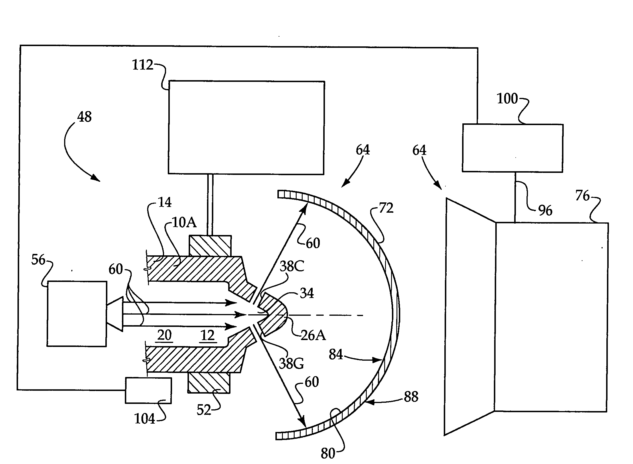
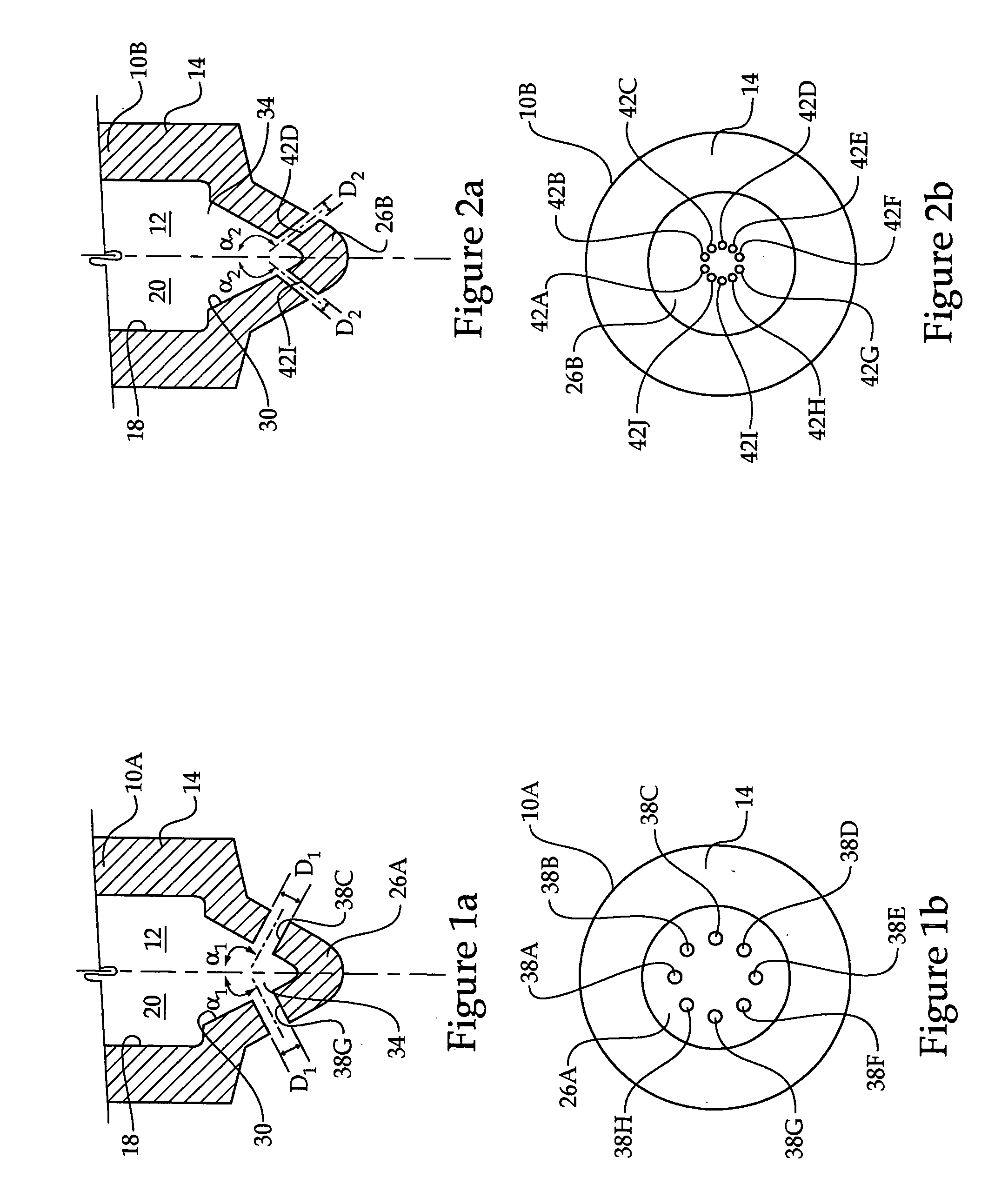
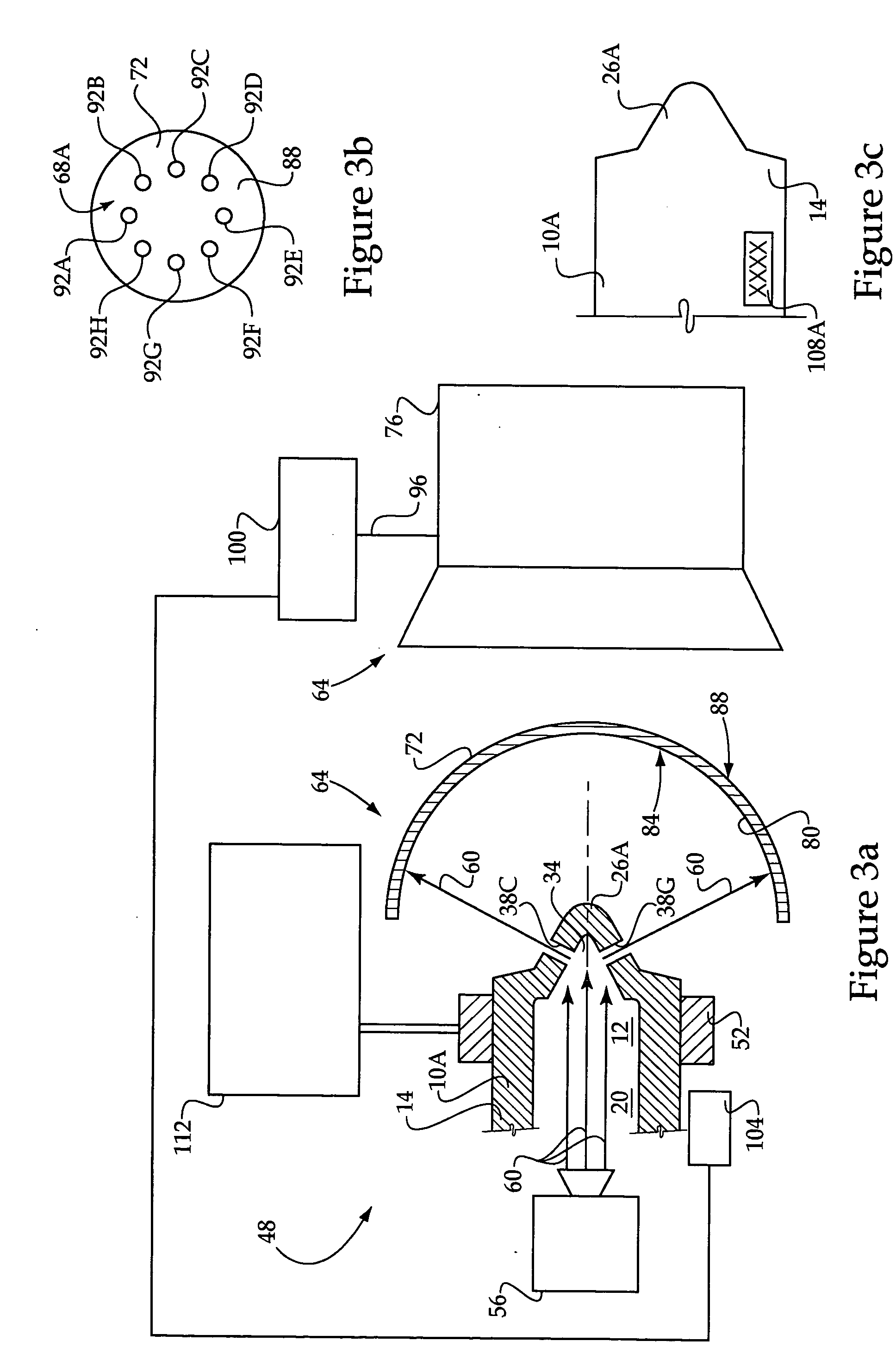
[0023]Referring to FIGS. 1a and 1b, a first fuel injector nozzle 10A for a compression-ignition engine defines a fuel chamber 12. The first fuel injector nozzle 10A is characterized by a generally cylindrical portion 14 having an inner surface 18 that defines a cylindrical portion 20 of the fuel chamber 12. The first fuel injector nozzle 10A is also characterized by a g...


PUM


Abstract

A sorting apparatus includes a nozzle, a light source, and a light receiver. The nozzle is positioned with respect to the light source and the light receiver such that light from the light source travels through holes defined by the nozzle and onto the light receiver, thereby to create a light pattern. The light pattern may be analyzed to sort the nozzle into one of several categories. A corresponding method is also provided.

Description

TECHNICAL FIELD[0001]This disclosure relates to sorting nozzles and other similar components, and more particularly to sorting by projecting electromagnetic radiation through holes defined by the nozzle or other component to create a light pattern that can be detected on a light receiver.BACKGROUND[0002]A fuel injector for a compression ignition engine includes a nozzle defining a plurality of holes through which fuel is injected into a combustion chamber at high pressure. The holes are typically microscopic, often less than 300 micrometers in diameter. Accordingly, even if the holes are visible, ascertaining the quantity of holes, the angular orientation of the holes, and the sizes of the holes is difficult, if not impossible, to perform visually, especially in high-volume commercial operations such as nozzle manufacturing or remanufacturing.[0003]However, it is desirable to sort nozzles based on their hole configurations. For example, during nozzle manufacturing, it is desirable t...

Claims


Application Information

Patent Timeline
IPC IPC(8): B07C5/02
CPCB07C5/04F02M65/00F02M61/1846
Inventor REBINSKY, DOUGLAS A.
Owner CATERPILLAR INC
Why Eureka
Eureka Blog
Learn More