Electronically actuated apparatus using solenoid actuator with integrated sensor

a solenoid actuator and actuator technology, applied in the direction of magnets, magnet bodies, magnetic bodies, etc., can solve the problem that the components of the electromagnetic actuator can be relatively expensiv

Active Publication Date: 2008-02-21
AMERICAN AXLE & MFG
View PDF72 Cites 62 Cited by
  • Summary
  • Abstract
  • Description
  • Claims
  • Application Information

AI Technical Summary

Problems solved by technology

It will be appreciated that such electromagnetically actuated driveline components can be relatively expensive due to the complexity of the sensor target and the labor required for setting the position of the sensor.

Method used


Image

  • Electronically actuated apparatus using solenoid actuator with integrated sensor
  • Electronically actuated apparatus using solenoid actuator with integrated sensor
  • Electronically actuated apparatus using solenoid actuator with integrated sensor

Examples


Embodiment Construction

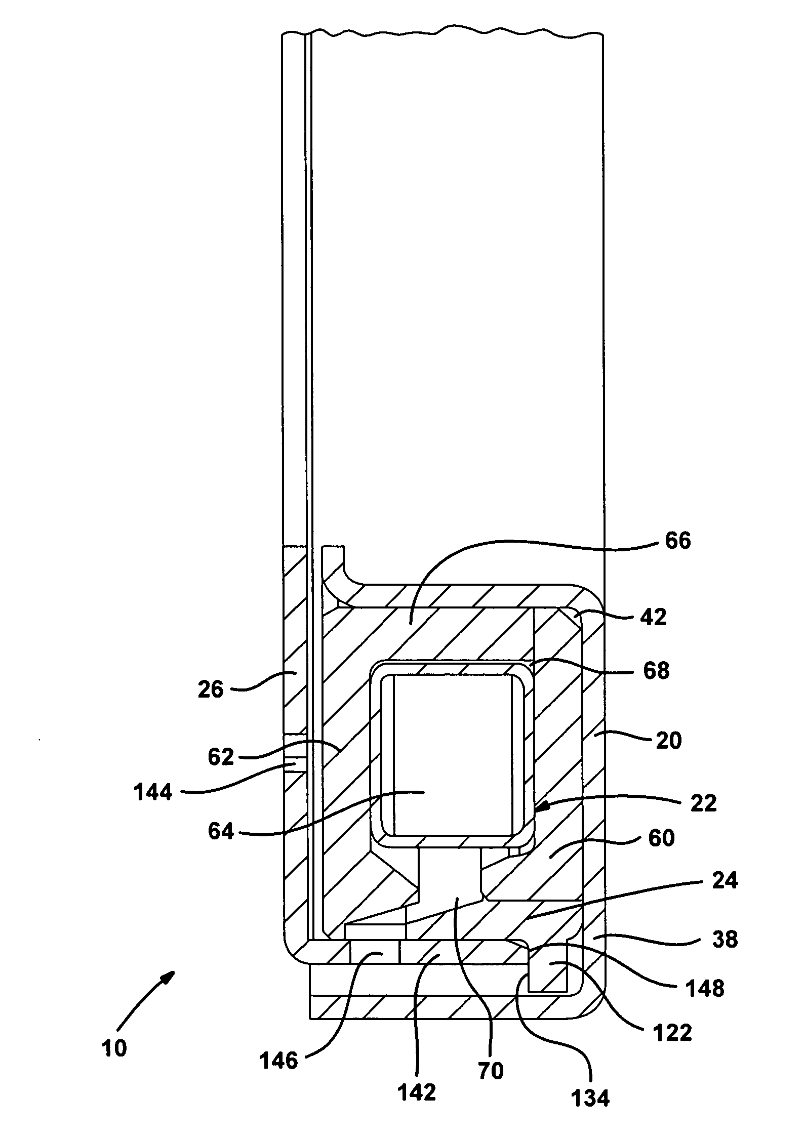
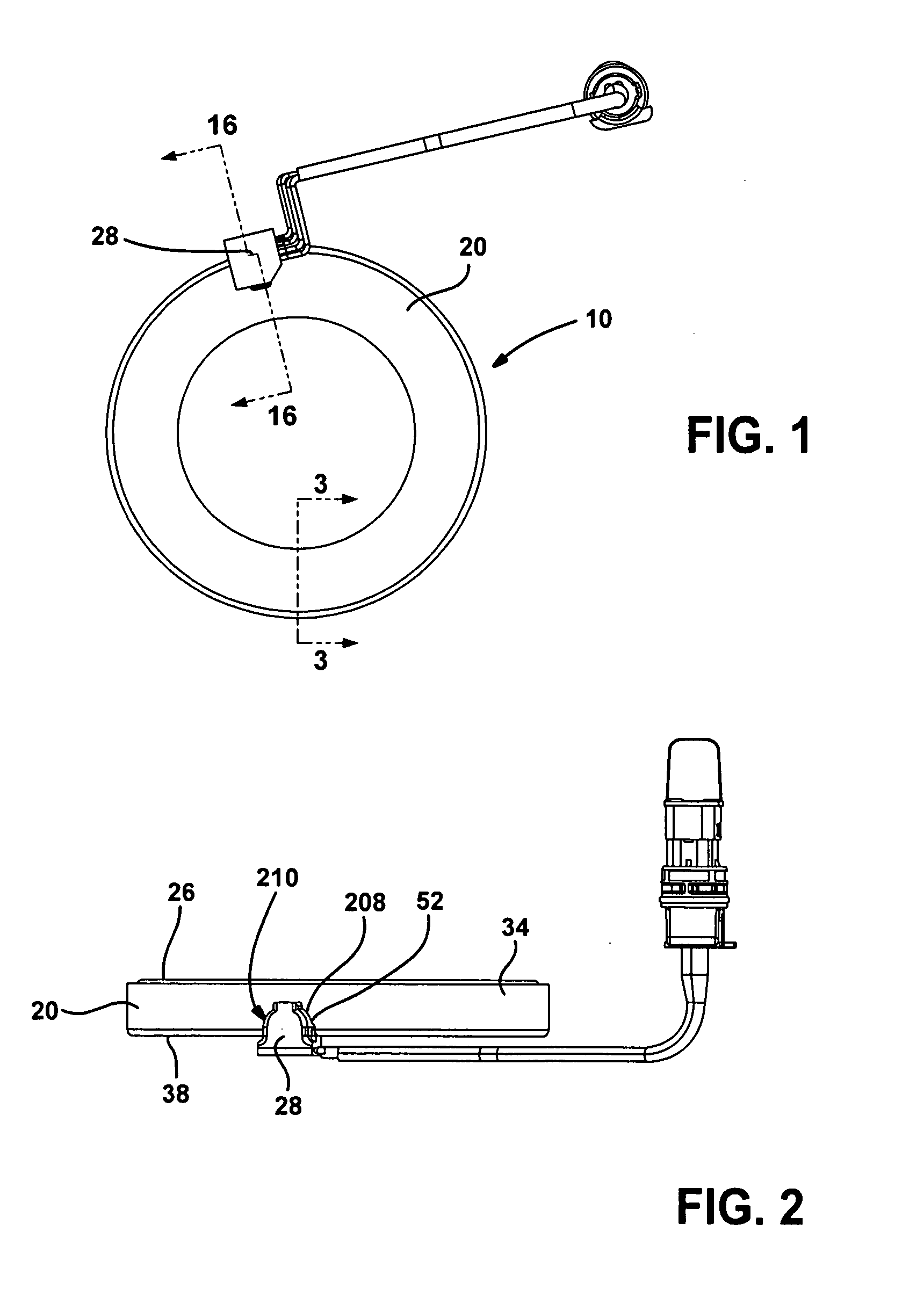
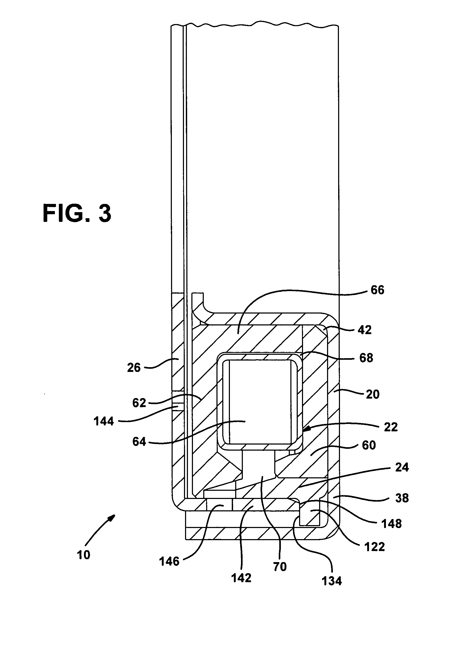
[0043]With reference to FIGS. 1 through 3 of the drawings, an actuator assembly constructed in accordance with the teachings of the present invention is generally indicated by reference numeral 10. The actuator assembly 10 can include a frame 20, a coil assembly 22, an armature 24, a plunger 26 and a sensor assembly 28.

[0044]With reference to FIGS. 4 through 6, the frame 20 can be formed of a suitable material, such as a material having a low magnetic susceptibility (e.g., 316 stainless steel), and can include an outer or first annular sidewall 34, an inner or second annular sidewall 36, an endwall 38 and a sensor mount 40. The endwall 38 can be coupled to the first and second annular sidewalls 34 and 36 so as to define an interior annular recess 42 that is bounded on three sides by the first and second sidewalls 34 and 36 and the endwall 38. The second annular sidewall 36 can define a through-hole 44 and may optionally include a lip portion 46 that extends radially inwardly to some...


PUM

PropertyMeasurementUnit
angleaaaaaaaaaa
angleaaaaaaaaaa
angleaaaaaaaaaa

Abstract

An electromagnetic actuator assembly that includes an annular frame, a coil assembly, an annular armature, a plunger and a sensor. The coil assembly is coupled to the frame and includes an annular core and an annular coil. The annular armature is received in the frame and abutted against the plunger. A sensor target can be coupled to the armature or the plunger and includes a radially outwardly extending sensor target. The sensor is coupled to the frame and configured to sense a position of the sensor target. A method for operating an electromagnetic actuator is also provided.

Description

INTRODUCTION[0001]The present disclosure generally relates electronically actuated driveline components such as differentials and transfer cases. More particularly, the present disclosure relates to an electronically actuated driveline component that employs a solenoid actuator with an integrated sensor.[0002]It is known in the vehicle axle art to employ an electromagnetic actuator to translate members of an assembly into / out of engagement with one another. For example, commonly owned U.S. Pat. No. 6,958,030 discloses an electromagnetic locking differential assembly that employs an electromagnetic actuator to selectively couple a side gear to a differential case to cause the differential assembly to operate in a fully locked condition. More specifically, the electromagnetic actuator is actuated to axially translate an actuating ring (which is non-rotatably coupled to the differential case) such that dogs on the actuating ring matingly engage dogs that are formed on a face of the sid...

Claims


Application Information

Patent Timeline
Patent Type & Authority Applications(United States)
IPC IPC(8): H01F3/00
CPCF16H48/08F16H48/24F16H48/30F16H48/34F16H48/40Y10T29/49826F16H2048/346H01F7/1638H01F27/402H01F2007/185F16H2048/204F16D2027/002F16D27/118
Inventor YORK, TODD MICHAELPINKOS, ANDREW FRANK
Owner AMERICAN AXLE & MFG
Why Eureka
Try Eureka