Illumination devices

a technology of light beams and insulating devices, which is applied in the direction of lighting and heating apparatuses, instruments, condensers, etc., can solve the problems of limiting the use of general lighting applications, uncollimated light from sources which do not strike the reflectors, and poor quality of far field beams of ligh

Active Publication Date: 2008-02-21
VIAVI SOLUTIONS INC
View PDF18 Cites 210 Cited by
  • Summary
  • Abstract
  • Description
  • Claims
  • Application Information

AI Technical Summary

Benefits of technology

[0005]Accordingly, it is one object of the present invention to provide lighting devices that utilize small, wide-angle light sources, such as an LEDs, in combination with a colli

Problems solved by technology

Also, the quality of the beam of light in the far field is poor, forming a ring structure caused by the base of the reflector being blocked by the light source.
An additional drawback of reflective parabolic structure designs is that the light from the source which does not strike the reflector propagates out the open end of the reflector un-collimated.
Since true collimation of all the light from such an arrangement cannot be achieved, such designs compromise between the divergence of the light and the uniformity of the resulting beam.
This limits their use for general lighting applications without the use of some diffuser or ot

Method used


Image

  • Illumination devices
  • Illumination devices
  • Illumination devices

Examples


Embodiment Construction

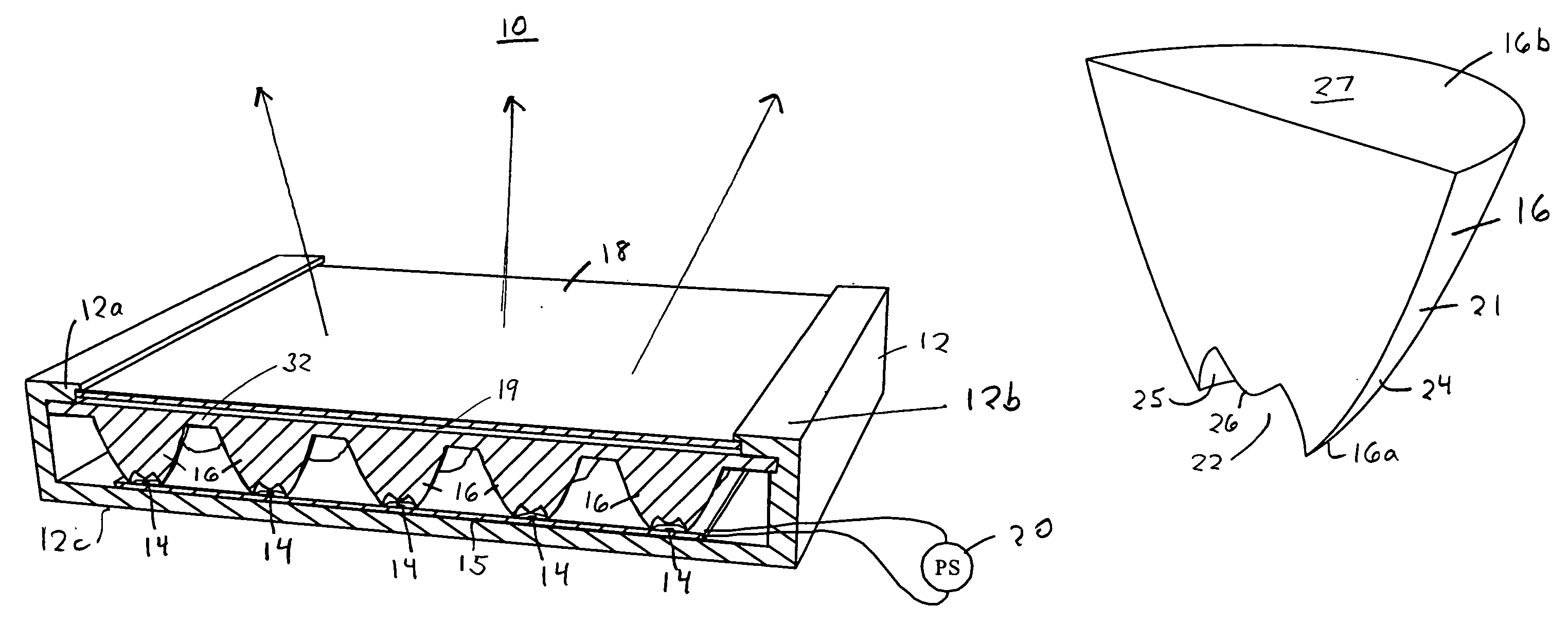
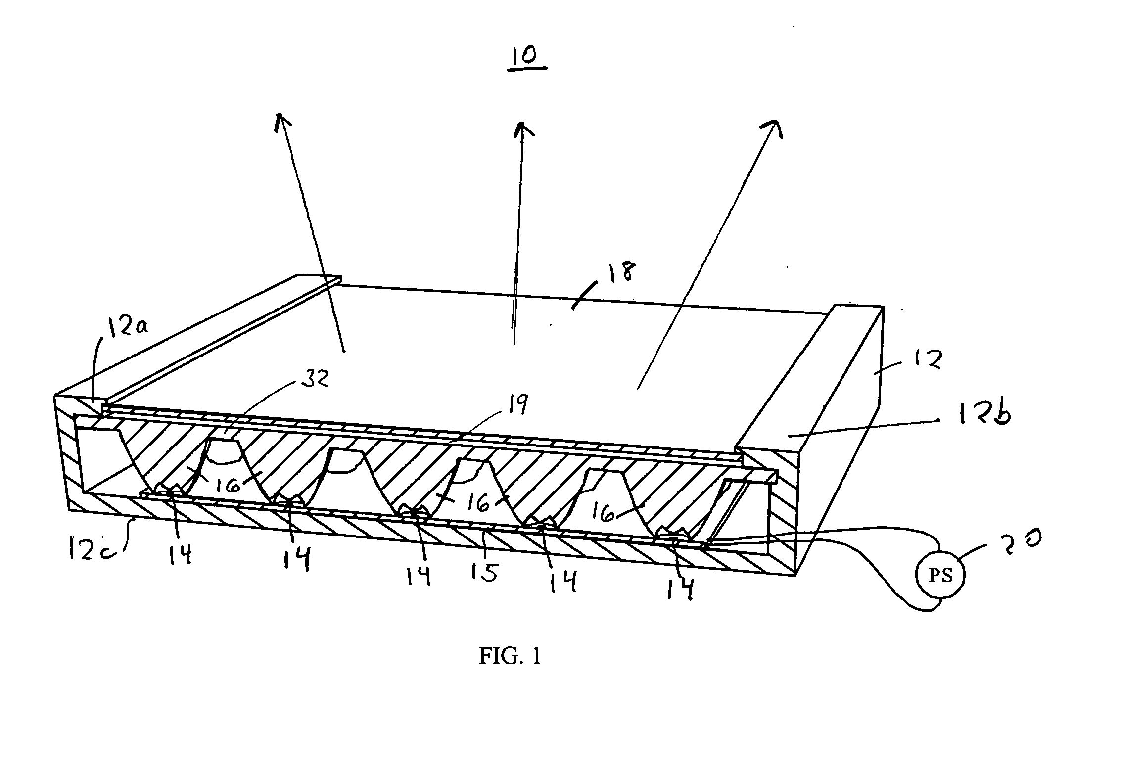
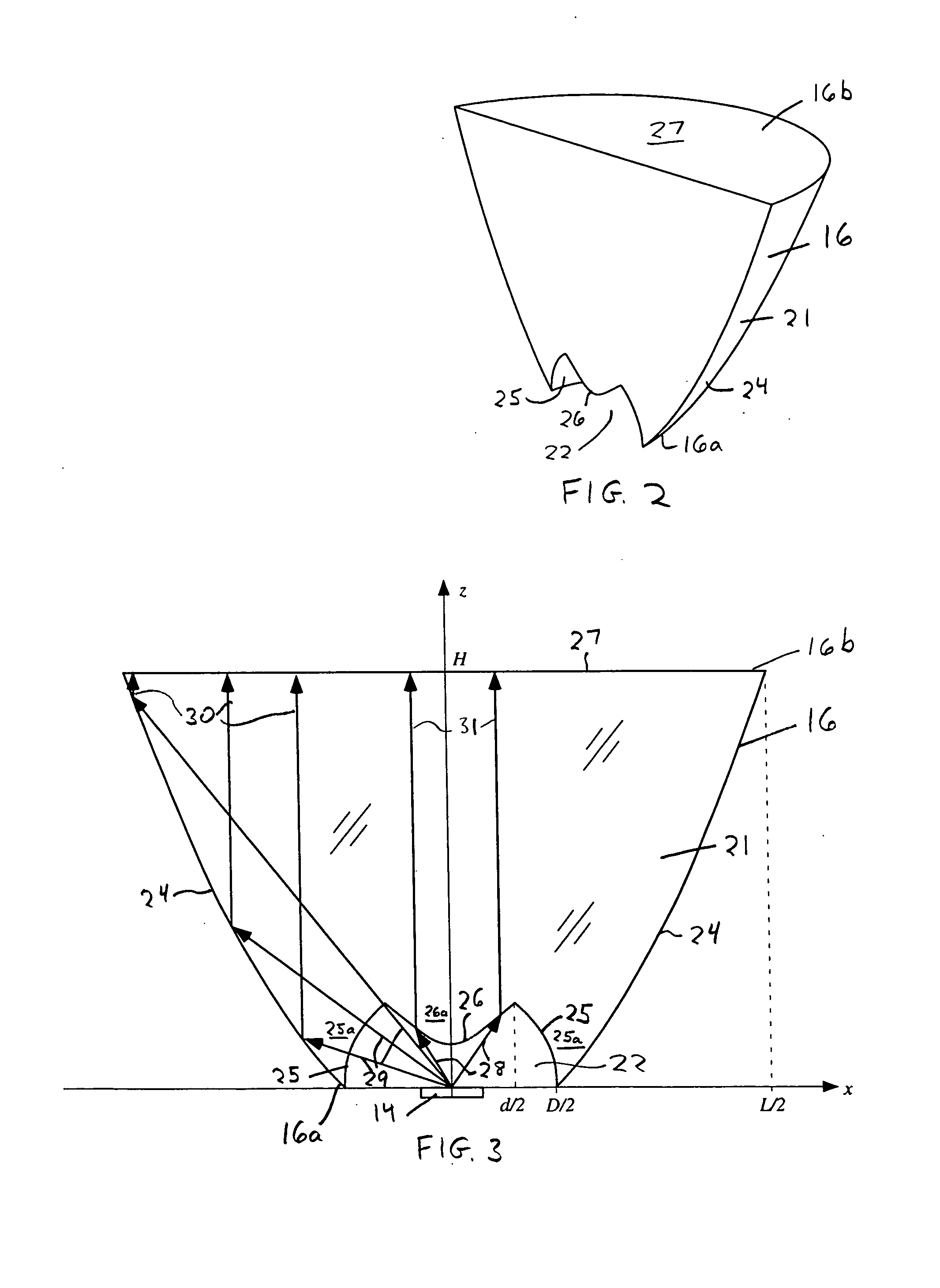
[0038]Referring to FIG. 1, one example of a lighting device 10 of the present invention is shown enclosed in a housing 12. The lighting device 10 has multiple wide angle light sources 14, such as LEDs, mounted on a circuit board 15 which are disposed to provide light to a two-dimensional array of parabolic shaped collimators 16 disposed along interior of the housing. The collimators 16 each partially collimates the light for each of their respective light sources 14, and provides such partially collimated light to a diffuser 18 spaced by a gap 19 from the array of collimators. Partially collimated light represents light having an angular distribution intensity narrower than the light source 14, and may particularly refer to light having an angular distribution intensity with collimated or bright central portion and non-collimated light portions of decreasing light intensity at increasing angles, e.g., ±10°, from the central portion (see, examples of collimator distribution intensity...


PUM


Abstract

Lighting devices are provided for efficiently distributing light over an area to provided uniform illumination over a wide angle or other tailored illumination patterns. Each light device has at least one light source, at least one collimator for partially collimating light from the light source, and at least one diffuser for diffusing light from the collimator. The diffuser provides diffused light over an area from the diffuser having an intensity that is angularly dependent in accordance with the angular distribution intensity of light outputted from the collimator, so as to provide a predetermined illumination pattern from the device. The light sources and collimators may be provided in one or two-dimensional arrays, and a single diffuser may be formed on each collimator or the diffuser may be along a plate spaced from the collimators.

Description

FIELD OF THE INVENTION[0001]The invention relates to illumination devices, often called luminaires, and in particular to illumination devices using small light sources, such as light-emitting diodes (LEDs) or the like, for the efficient and controlled illumination of a desired area. The illumination devices of the present invention may be utilized for general-purpose lighting in and around homes and commercial buildings, and may also be used in architectural and industrial lighting applications.BACKGROUND OF THE INVENTION[0002]Devices have been developed for collecting and collimating light from a small light source, such as an incandescent, LED, or the like. Often such devices use a reflective parabolic structure which are designed to collimate the light from a point source placed at the focus of the reflector due to the divergent nature of the light source. The light striking the structure is redirected parallel to the axis of the parabola, exits out the open end of the reflector,...

Claims


Application Information

Patent Timeline
IPC IPC(8): F21V1/00
CPCF21V5/007F21V5/04F21V7/0091F21Y2101/02F21Y2103/003F21Y2105/001F21V29/83G02B19/0066G02B19/0028F21S8/033F21S8/04F21V29/507F21V17/002F21Y2105/10F21Y2103/10F21Y2115/10F21Y2105/14
Inventor CHAKMAKJIAN, STEPHEN H.SCHERTLER, DONALD J.SALES, TASSOMORRIS, G. MICHAEL
Owner VIAVI SOLUTIONS INC
Why Eureka
Try Eureka