
Memory power management

Active Publication Date: 2008-02-21
III HLDG 1
View PDF35 Cites 10 Cited by
  • Summary
  • Abstract
  • Description
  • Claims
  • Application Information

AI Technical Summary

Problems solved by technology

However, conventional memory systems are problematic because of the need to increase functionality while reducing die sizes.
However, conventional implementations use large circuit patterns that require large die sizes.
Due to conventional circuit patterns and component design, power requirements and heat generation are high, which lead to memory system failures and errors.
Another issue with conventional implementations is the amount of driving voltage required to program and erase memory cells or elements (“elements”) in conventional memory arrays.
The voltages generated by conventional charge pumps are limited by factors such as the amount of available current, the size of capacitors used in a charge pump circuit, and the quantity of charge pumps used to generate voltages for the programmable sequences.
Further, as conventional memory arrays increase in capacity, the size of conventional charge pumps and the required amount of driving voltages also increase.
Combined with conventional charge pumps, conventional memory systems are difficult and expensive to manufacture and operate.
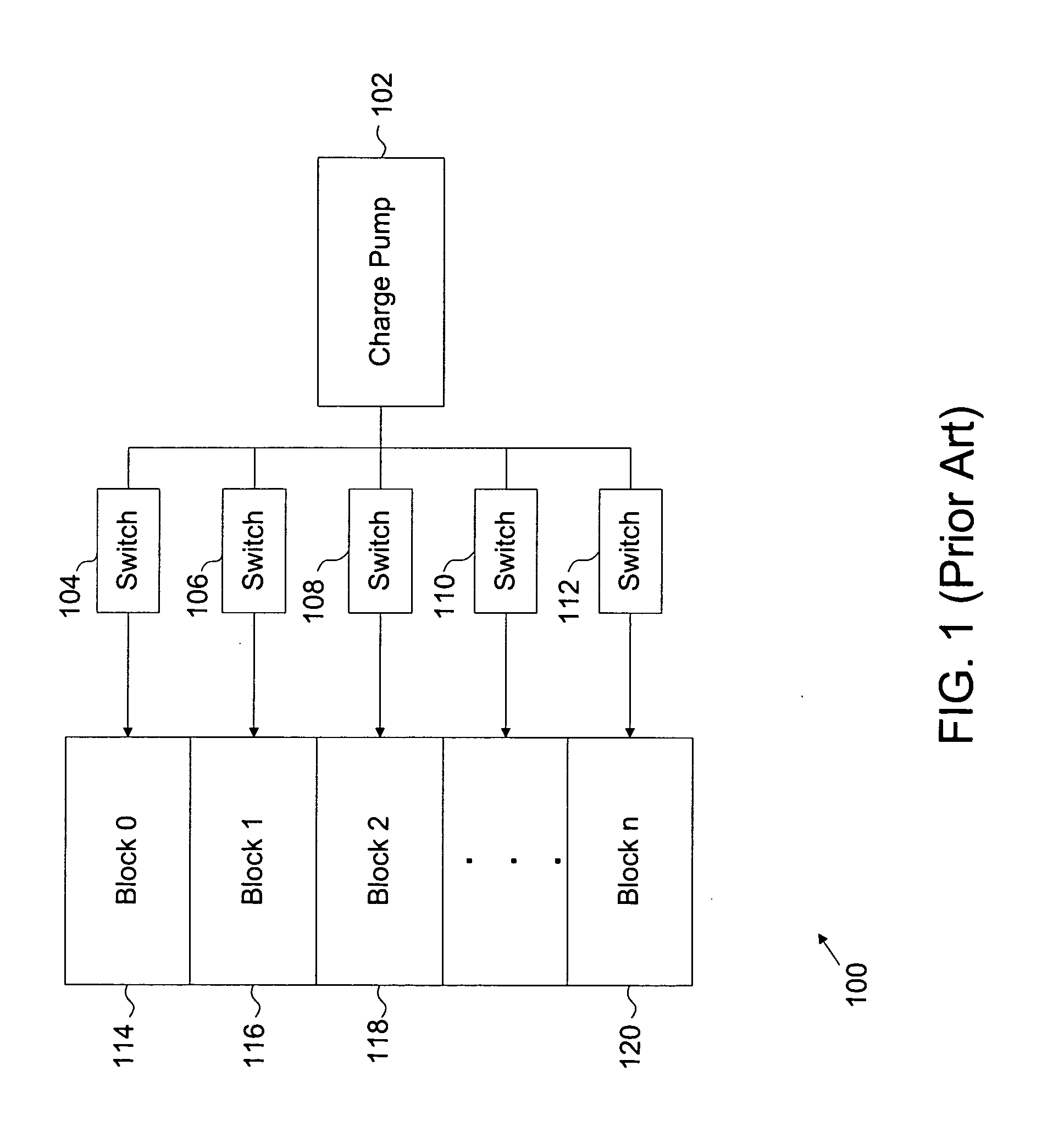
However, large voltages generated by charge pump 102 can create disturbances or “disturb effects” in surrounding elements other than those desired.
Conventional memory systems suffer from large charge pump sizes and outputs, which require large die sizes, create error and disturb effects, and increase fabrication and operational expenses.

Method used


Image

  • Memory power management
  • Memory power management
  • Memory power management

Examples


Embodiment Construction

[0019]The invention can be implemented in numerous ways, including as a system, a process, an apparatus, or a series of program instructions on a computer readable medium such as a computer readable storage medium or a computer network where the program instructions are sent over optical or electronic communication links. In general, the steps of disclosed processes may be performed in an arbitrary order, unless otherwise provided in the claims.

[0020]A detailed description of one or more embodiments is provided below along with accompanying figures. The detailed description is provided in connection with such embodiments, but is not limited to any particular example. The scope is limited only by the claims, and numerous alternatives, modifications, and equivalents are encompassed. Numerous specific details are set forth in the following description in order to provide a thorough understanding. These details are provided for the purpose of example and the described techniques may be ...


PUM


Abstract

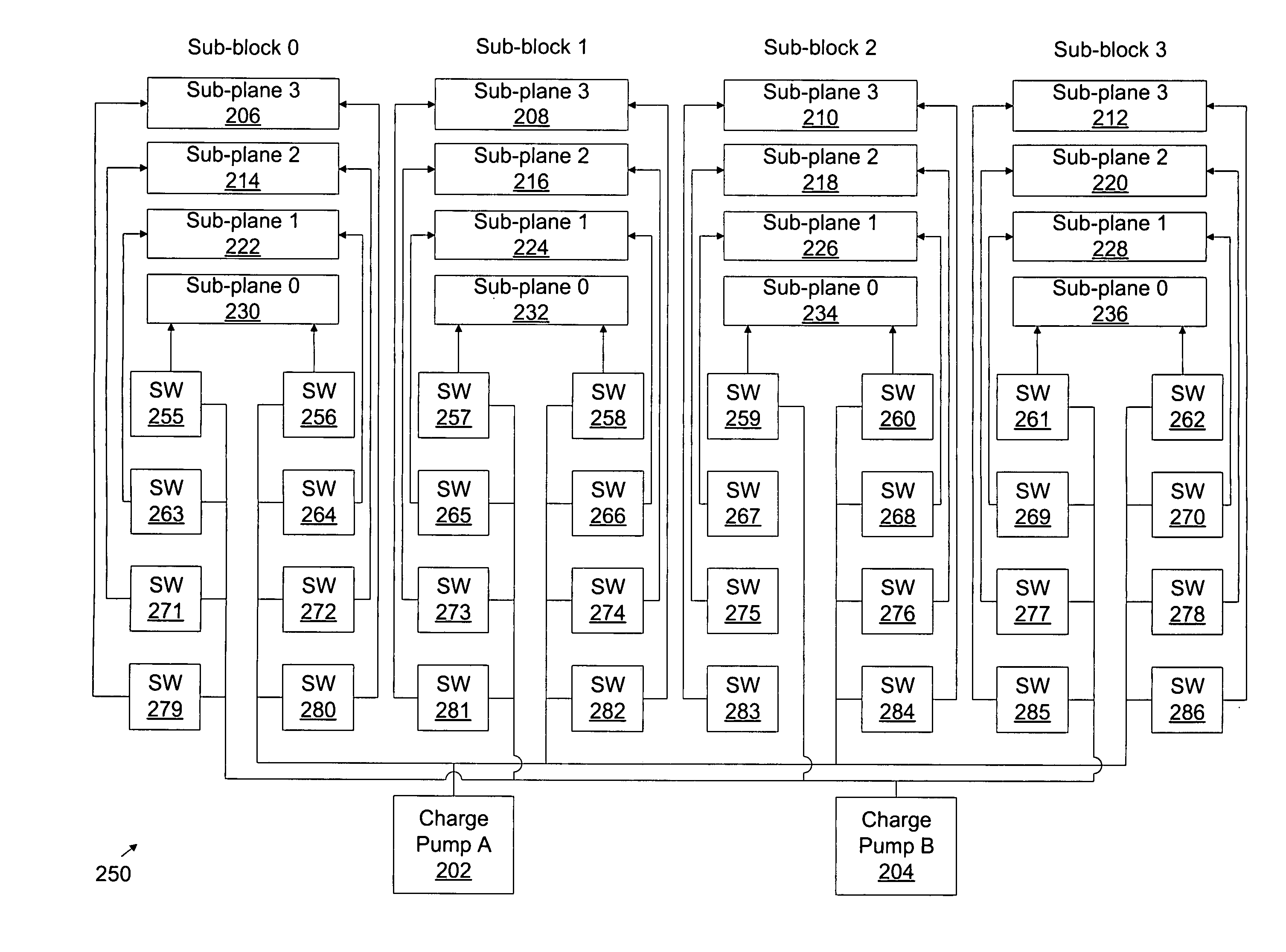
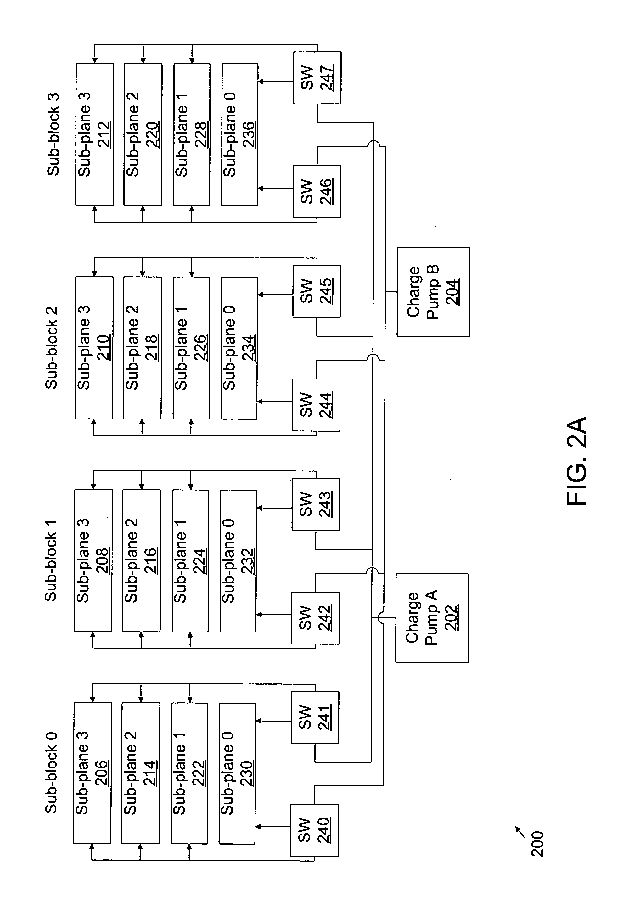
Memory power management is described. A non-volatile memory array is provided, the array including separately controlled memory blocks. At least two charge pumps are coupled to the array, the charge pumps being configured to provide at least two voltages. Logic is configured to control how the voltages are delivered to the memory blocks.

Description

FIELD OF THE INVENTION[0001]The present invention relates generally to semiconductors and memory technology. More specifically, memory power management is described.BACKGROUND OF THE INVENTION[0002]Conventional memory systems (e.g., storage systems, disk drives, hard disks, memory chips, memory devices, and the like) are fabricated using technologies such as static random access memory (SRAM), dynamic random access memory (DRAM), or non-volatile implementations (e.g., Flash). However, conventional memory systems are problematic because of the need to increase functionality while reducing die sizes.[0003]Memory controllers, logic circuitry, or other components in conventional implementations often require large die sizes in order to accommodate various components or circuits. Conventional implementations often use components such as multiple processors, buffer memory, error correction code (ECC), and direct memory access (DMA) circuits for fast movement of data. Demands for increasin...

Claims


Application Information

Patent Timeline
IPC IPC(8): G11C5/14
CPCG11C5/145G11C5/02
Inventor NORMAN, ROBERT
Owner III HLDG 1
Learn More