Ruggedized fiber optic connector assembly

Active Publication Date: 2008-02-21
CORNING OPTICAL COMM LLC
View PDF32 Cites 193 Cited by
  • Summary
  • Abstract
  • Description
  • Claims
  • Application Information

AI Technical Summary

Benefits of technology

[0010]In one embodiment of the present invention, a ruggedized fiber optic connector assembly includes a substantially hollow plug housing; and a retention body disposed within the substantially hollow plug housing; wherein the retention body includes a first portion that is configured to engage and retai

Problems solved by technology

As of yet, however, there is an unresolved need for an alternative (or additional) retention method for dealing with otherwise incompatible drop cable strength members, such as glass-reinforced plastic (GRP) strength members and the like.
Further, this crimp desi

Method used


Image

  • Ruggedized fiber optic connector assembly
  • Ruggedized fiber optic connector assembly
  • Ruggedized fiber optic connector assembly

Examples


Embodiment Construction

[0022]Reference will now be made in detail to the preferred embodiments of the present invention, examples of which are illustrated in the accompanying drawings. Whenever possible, like reference numbers will be used to refer to like components or parts.

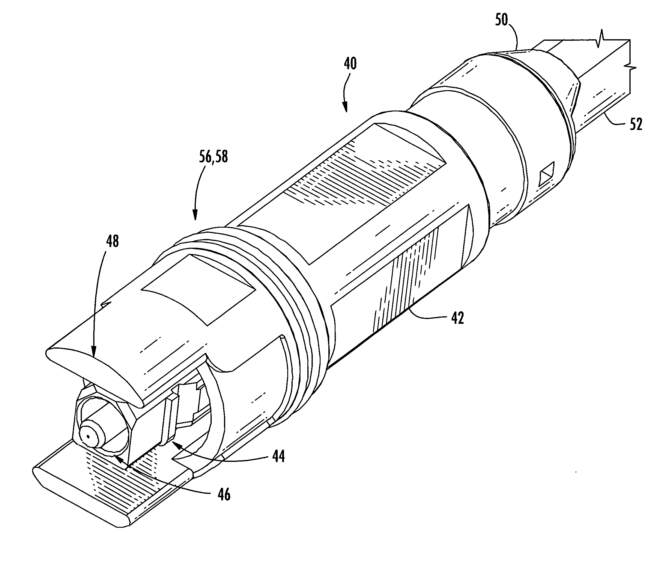
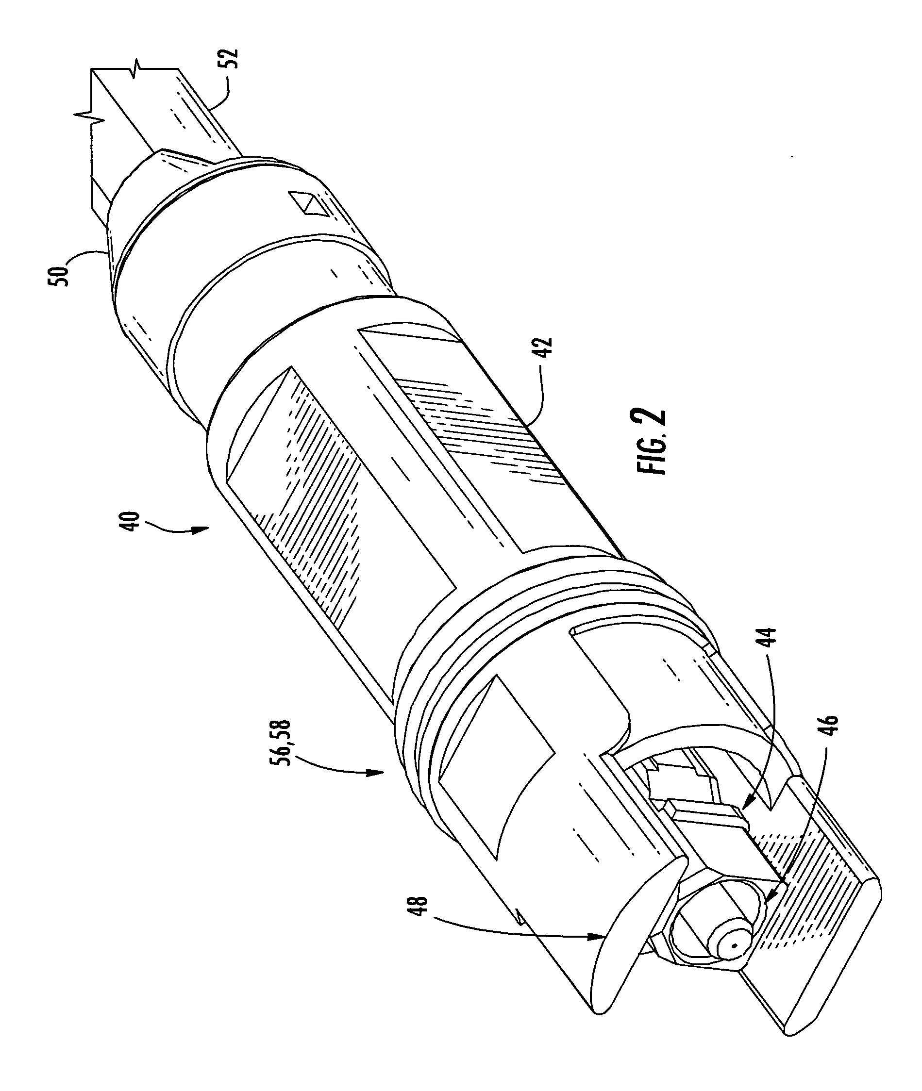
[0023]Referring to FIG. 2, the connector assembly 40, also referred to herein as a “plug”, of the present invention includes a plug housing 42 that contains a connector sub-assembly 44 (i.e., a pre-assembled ferrule holder module), the connector sub-assembly 44 holding a ferrule 46. The connector sub-assembly 44 and ferrule 46 are accessible through one open end of the plug housing 42, such that the ferrule can be optically connected to the ferrule of a receptacle or another connector assembly, or plug. The shrouding fingers 48 of the connector assembly 40 are reduced in length as compared to the conventional connector 10 (FIG. 1) in order to allow two connector assemblies to better mate with one another, among other things. Any redu...


PUM


Abstract

A ruggedized fiber optic connector assembly includes a substantially hollow plug housing; and a glue body disposed within the substantially hollow plug housing; wherein the glue body includes a first portion that is configured to engage and retain an optical cable comprising an optical fiber and one or more strength members; wherein the glue body includes a second portion that is configured to engage and retain a connector sub-assembly comprising an optical ferrule; wherein the second portion of the glue body includes a pair of opposed snap hooks that are configured to engage a corresponding pair of opposed recesses of the connector sub-assembly; and wherein the optical fiber and the optical ferrule are optically coupled.

Description

BACKGROUND OF THE INVENTION[0001]1. Field of the Invention[0002]The present invention relates generally to a ruggedized fiber optic connector assembly, also referred to as a fiber optic “plug.” More specifically, the present invention relates to a ruggedized fiber optic connector assembly that incorporates a retention body, or glue body, that is configured to both retain a fiber optic cable, preferably having one or more strength members, and engage a fiber optic receptacle or, alternatively, another fiber optic connector assembly.[0003]2. Technical Background of the Invention[0004]Optical fiber is increasingly being used for a variety of broadband applications, including voice, video, and data transmission. As a result, fiber optic communications networks include a number of interconnection points at which multiple optical fibers are interconnected. Fiber optic communications networks also include a number of connection terminals, examples of which include, but are not limited to, ...

Claims


Application Information

Patent Timeline
IPC IPC(8): G02B6/38G02B6/36
CPCG02B6/3887G02B6/3869G02B6/3889
Inventor LUTHER, JAMES P.THEUERKORN, THOMASLIU, XIN
Owner CORNING OPTICAL COMM LLC
Why Eureka
Try Eureka