Portable bailer

a bailer and portability technology, applied in the direction of pump components, piston pumps, positive displacement liquid engines, etc., can solve the problems of high damage to external electrical wiring between batteries and pumps, no prior art devices are suitable for watercraft use, and combination is extremely heavy and difficult to move. , to achieve the effect of simple portability

Inactive Publication Date: 2008-02-21
GOLIAT LAURA MARY
View PDF5 Cites 3 Cited by
  • Summary
  • Abstract
  • Description
  • Claims
  • Application Information

AI Technical Summary

Benefits of technology

[0006]The portable bailer of the present invention is preferably manually-operated through provision of an electrical switch preferably located upon an external handle either secured to or integral with an outer surface of the molded external housing. The switch is preferably a slide or a push button-type switch but may also be a toggle, or a rocker-type switch, or another suitable switch. The use of such a manual switch keeps the portable bailer simple and enables one to turn the pump on when the watercraft has accumulated water, and to turn the pump off when the watercraft has been bailed out.

Problems solved by technology

None of these prior art devices are suitable for use in watercraft such as an open-topped powerboat or rowboat where ease of operation, durability, portability, light-weightedness, and speed of removal of liquid from the watercraft is essential.
The prior art bailer also utilizes a 12-volt battery located outside the housing surrounding the pump rendering the combination extremely heavy and difficult to move.
It differs by having a bilge pump located at the distal end of the input section and having an output section intermediate the battery and the pump and also having external electrical wiring between the battery and the pump highly subject to damage.

Method used


Image

  • Portable bailer
  • Portable bailer
  • Portable bailer

Examples


Embodiment Construction

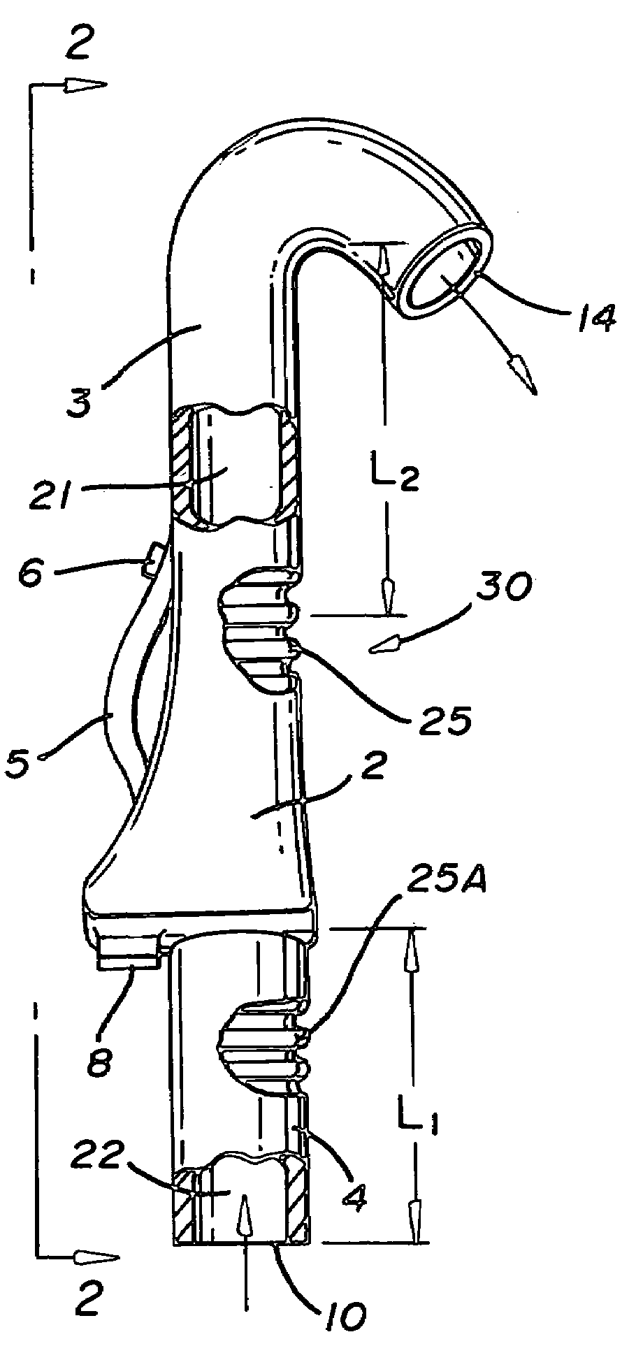
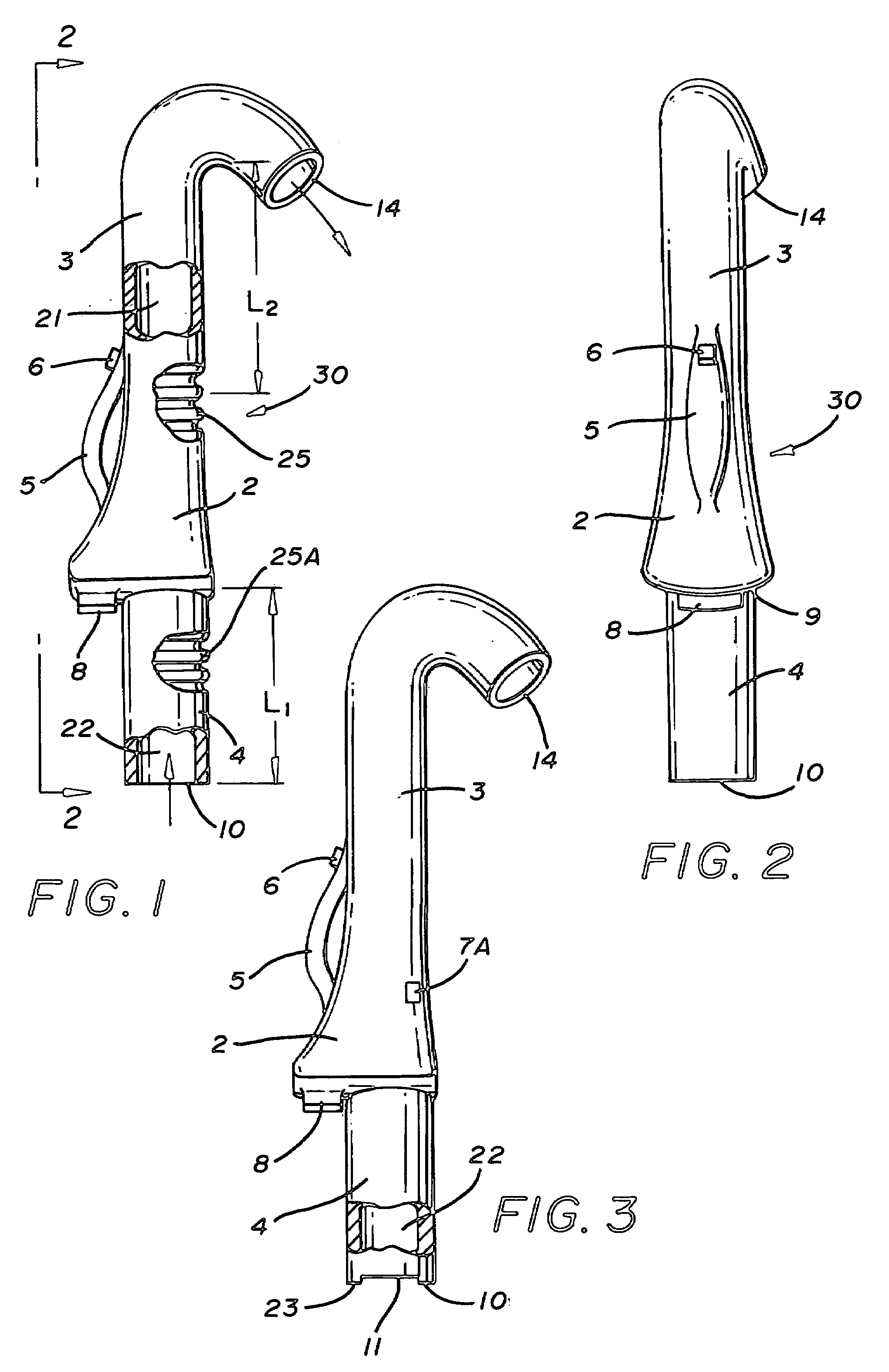
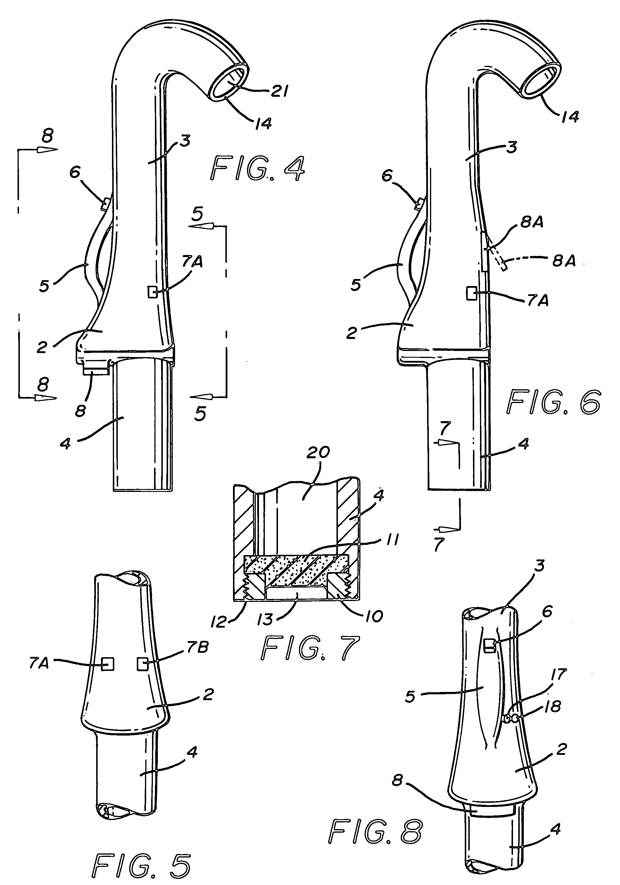
[0018]In FIG. 1, portable bailer 30 has a one-piece protective external molded housing comprising intermediate Section 2 surrounding a liquid pump and a power source such as a battery in close proximity to each other and from which extend an outlet or output Section 3 having an indeterminate length L2 and having a portion in close proximity to a distal end 14 formed into a substantial inverted J-like configuration. Section 3 has a liquid passageway 21 therethrough in liquid communication with the liquid pump. Bailer 30 also has an input or inlet Section 4 having an indeterminate length L1 and having a distal end 10. Inlet Section 4 has a liquid passageway 22 therethrough in liquid communication with the liquid pump. Although shown in the Figures as having a substantially tubular cross-sectional configuration, inlet Section 4 and / or outlet Section 3 may have any cross-sectional configuration provided that the bailer of the invention operates in the manner desired. Bailer 30 is also p...


PUM


Abstract

A portable bailer is used to remove liquid such as water from a watercraft, such as an open-topped powerboat or rowboat. The bailer features an electrically actuated liquid pump contained within a one-piece protective external molded housing also containing a suitable battery such as a suitable rechargeable battery in close proximity to the liquid pump and operative to provide power to the liquid pump upon actuation. The liquid pump and battery are located intermediate an elongated input section and an elongated output section of respective indeterminate lengths. A portion in close proximity to the distal end of the output section is formed into an inverted J-like configuration operative to direct the pumped liquid outwardly over the gunnel of the watercraft.

Description

FIELD OF THE INVENTION[0001]The present invention is directed generally to a portable bailer. More particularly, the present invention is directed to a portable bailer used to remove liquid such as water from watercraft such as an open-topped powerboat or rowboat. More specifically, the present invention is directed to a portable bailer including an electrically-operated liquid pump in close proximity to a power source such as a battery pack. The pump and battery pack are enclosed within a one-piece protective external molded housing intermediate elongated input section and an elongated output section of respective indeterminate lengths, with a portion in close proximity to a distal end of the output section formed into an inverted J-like configuration operative to direct the liquid over the gunnel of the watercraft. The pump is actuated by a manual switch preferably mounted on an external handle secured to or integral with an external surface of the molded housing.DESCRIPTION OF TH...

Claims


Application Information

Patent Timeline
Patent Type & Authority Applications(United States)
IPC IPC(8): F04B53/00
CPCF04B35/06
Inventor GOLIAT, LAURA MARY
Owner GOLIAT LAURA MARY
Why Eureka
Try Eureka