
Transmission of a power loss condition over a network

a technology of power loss and transmission condition, applied in the direction of transmission monitoring, frequency-division multiplex, instruments, etc., can solve the problems of low efficiency of systems that employ this approach, high cost of energy storage, and resource waste,

Active Publication Date: 2008-02-21
CISCO TECH INC
View PDF0 Cites 15 Cited by
  • Summary
  • Abstract
  • Description
  • Claims
  • Application Information

AI Technical Summary

Benefits of technology

This approach minimizes downtime by quickly identifying power failures, releasing reserved resources, and sustaining the network interface for the necessary time to send the dying gasp message, potentially reducing costs and energy storage needs.

Problems solved by technology

In the event of a power failure such resources may be wasted as the resources may continue to be reserved for systems that have experienced a power failure and are no longer capable of communicating.
Because of the increasing power demands of high-bandwidth xDSL chipsets such as ADSL2 / + and G.SHDSL chipsets, the amount of energy storage required to sustain the 40-50 ms of uptime may be expensive.
However, many systems that employ this approach have been found to suffer from low efficiency.
Other implementations such as switchers are much more efficient but are also more expensive.
These conflicting design constraints make the implementing of a cost effective dying gasp system challenging.
It should be appreciated that although very large capacitors may be used to meet power demands, such approaches may be space and cost prohibitive.

Method used


Image

  • Transmission of a power loss condition over a network
  • Transmission of a power loss condition over a network
  • Transmission of a power loss condition over a network

Examples


Embodiment Construction

[0015] Reference will now be made in detail to various embodiments of the invention, examples of which are illustrated in the accompanying drawings. While the invention will be described in conjunction with these embodiments, it will be understood that they are not intended to limit the invention to these embodiments. On the contrary, the invention is intended to cover alternatives, modifications and equivalents, which may be included within the spirit and scope of the invention as defined by the appended claims. Furthermore, in the following description of the present invention, numerous specific details are set forth in order to provide a thorough understanding of the present invention. In other instances, well-known methods, procedures, components, and circuits have not been described in detail as not to unnecessarily obscure aspects of the present invention.

Notation and Nomenclature

[0016] Some portions of the detailed descriptions that follow are presented in terms of procedu...


PUM


Abstract

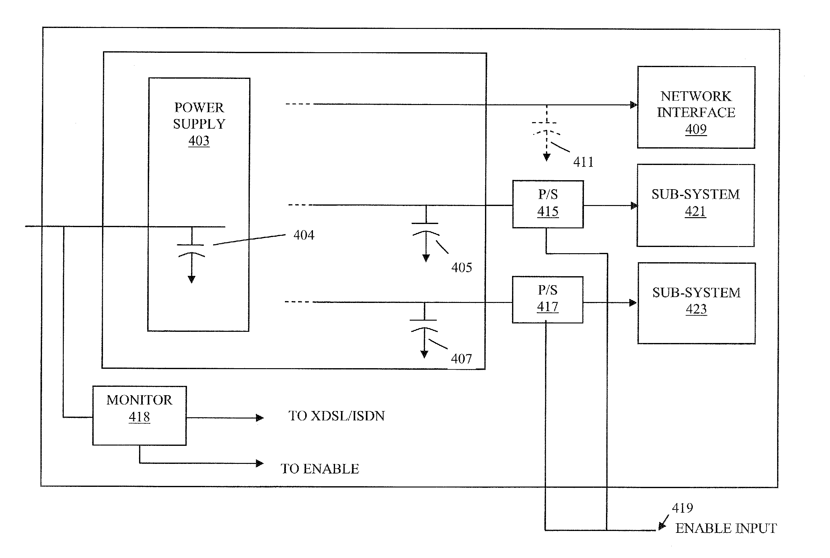
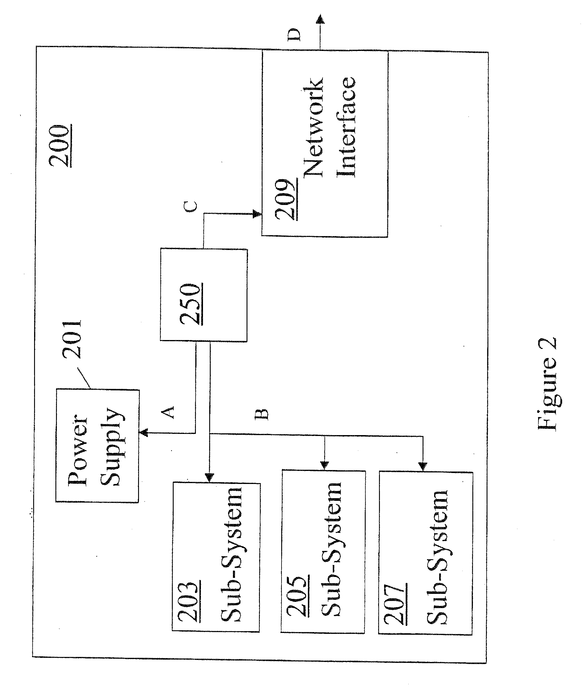
A system is disclosed as including a power supply, a secondary capacitive storage device connected to the power supply, and multiple network devices powered by the power supply. The system further includes a designated device for transmitting a power loss condition over a network, where upon detection of an imminent interruption of power from the power supply the secondary capacitive storage device exclusively powers the designated device during transmission of the power loss condition, and the multiple network devices are intentionally powered off.

Description

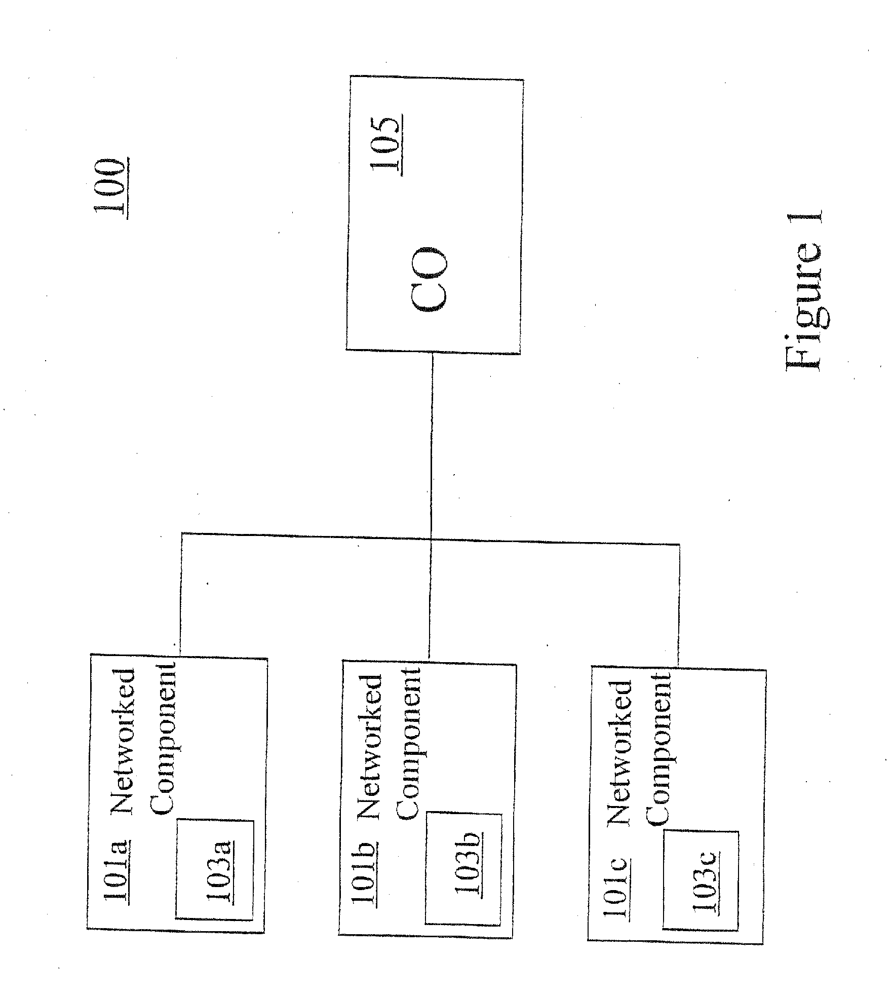
[0001] The present application is a divisional of U.S. patent application Ser. No. 11 / 182,161 entitled Method and System for Providing Dying Gasp Support for a Network Component, filed on Jul. 15, 2005, and which is herein incorporated by reference in its entirety.TECHNICAL FIELD [0002] Embodiments of the invention pertain to the transmission of a power loss condition over a network. BACKGROUND ART [0003] Computer networks provide an infrastructure that enables communication and exchange of information among computer systems that are coupled to the network. In many cases the individual networked systems may reserve resources to accommodate communications with the other networked systems to which they are coupled. In the event of a power failure such resources may be wasted as the resources may continue to be reserved for systems that have experienced a power failure and are no longer capable of communicating. [0004] Dying gasp features allow a message that details the imminent loss ...

Claims


Application Information

Patent Timeline
Patent Type & Authority Applications(United States)
IPC IPC(8): G06F1/30G06F15/173
CPCG06F1/30
Inventor CHUANG, TSU-YAU
Owner CISCO TECH INC
Learn More