
Motor control device

a technology of motor control and control device, which is applied in the direction of dynamo-electric converter control, multiple dynamo-motor starters, roofs, etc., can solve the problems of movable body deformation, movable body deformation, case, etc., and achieve the effect of preventing movable body deformation or breaking, reducing the influence of rotational speed, and eliminating the difference in rotation amoun

Inactive Publication Date: 2008-02-28
OMRON AUTOMOTIVE ELECTRONICS CO LTD
View PDF6 Cites 7 Cited by
  • Summary
  • Abstract
  • Description
  • Claims
  • Application Information

AI Technical Summary

Benefits of technology

[0007]In one or more embodiments of the present invention, a motor control device is capable of eliminating difference in rotation amounts between motors while suppressing influence on speed control.
[0009]In one or more embodiments of the present invention, the rotational speeds of a plurality of motors are detected and the average (average speed) thereof is calculated, and furthermore, the rotation amounts of a plurality of motors are detected and the average (average rotation amount) thereof is calculated. Regarding the rotational speed, each motor is controlled to operate at the target speed and rotated at the same speed by providing to each motor a drive command value calculated based on the target speed and the average speed. Regarding the rotation amount, the feedback signal is generated for each motor based on the calculated average rotation amount and the rotation amount of each motor, and control of the rotation amount is individually performed on each motor by changing the drive command value provided to each motor by the feedback signal. Therefore, the difference in rotation amounts is eliminated by independently controlling the rotation amounts while reducing the influence on the rotational speed to as little as possible. Since the rotational speeds and the rotation amounts are both made equal among the plurality of motors, imbalanced force will not act on the movable body when, for example, moving one movable body with two motors, thereby preventing the movable body from deforming or breaking.
[0010]According to one or more embodiments of the present invention, a motor control device is obtained in which the difference in the rotation amounts between the motors is eliminated while reducing the influence on the speed control as little as possible.

Problems solved by technology

However, when the rotational speeds and the rotation amounts (rotation angles) of the two motors differ due to variation in motor properties, variation in friction force of a link mechanism driven by the motors or difference in load of the motors caused by the tilt of the vehicle body, imbalanced force acts on the movable body, whereby the movable body may be deformed, or in an extreme case, broken.
Therefore, control to eliminate the difference in rotation amount while maintaining the rotational speeds equal between the motors cannot be carried out in conventional techniques.

Method used


Image

  • Motor control device
  • Motor control device
  • Motor control device

Examples


Embodiment Construction

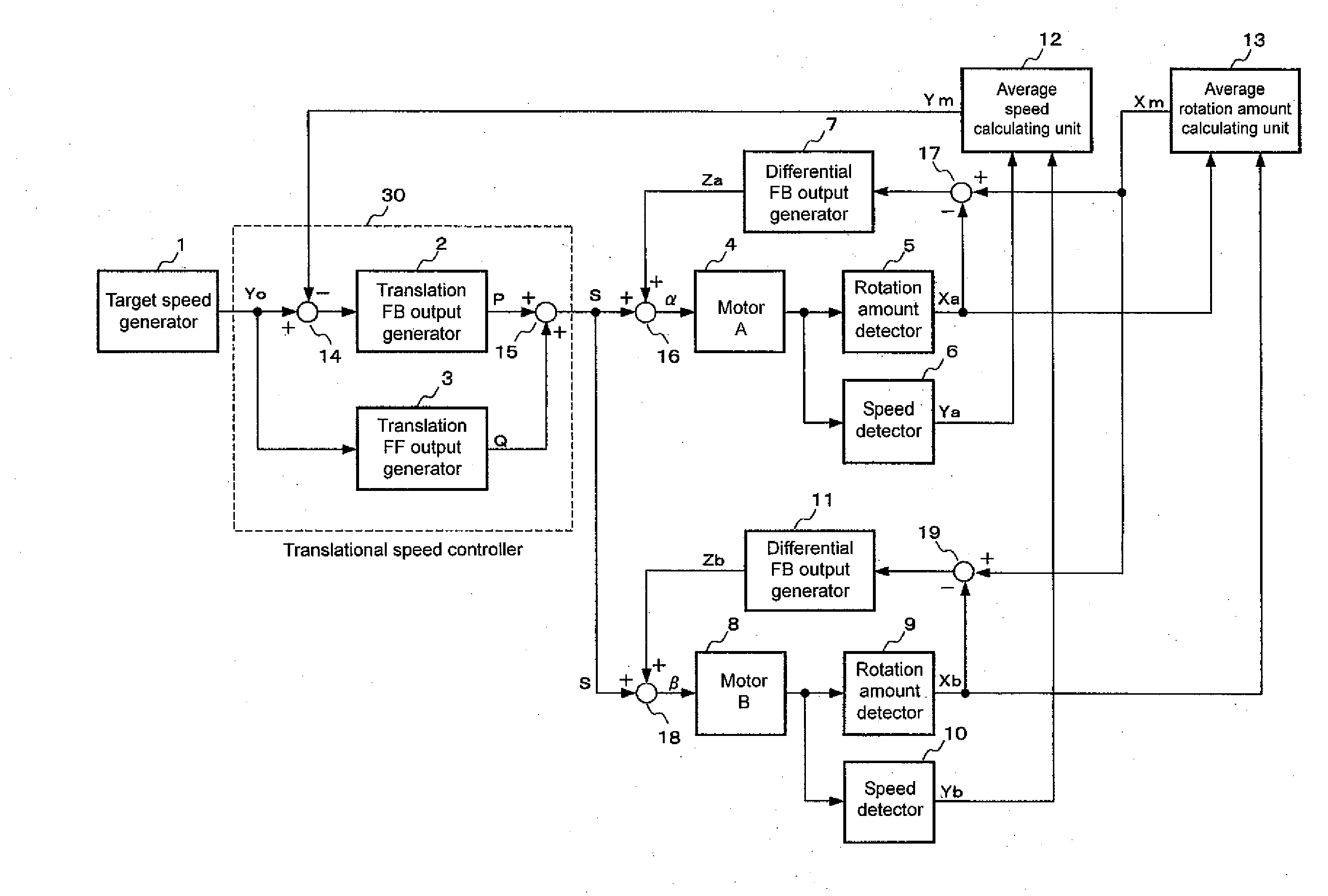
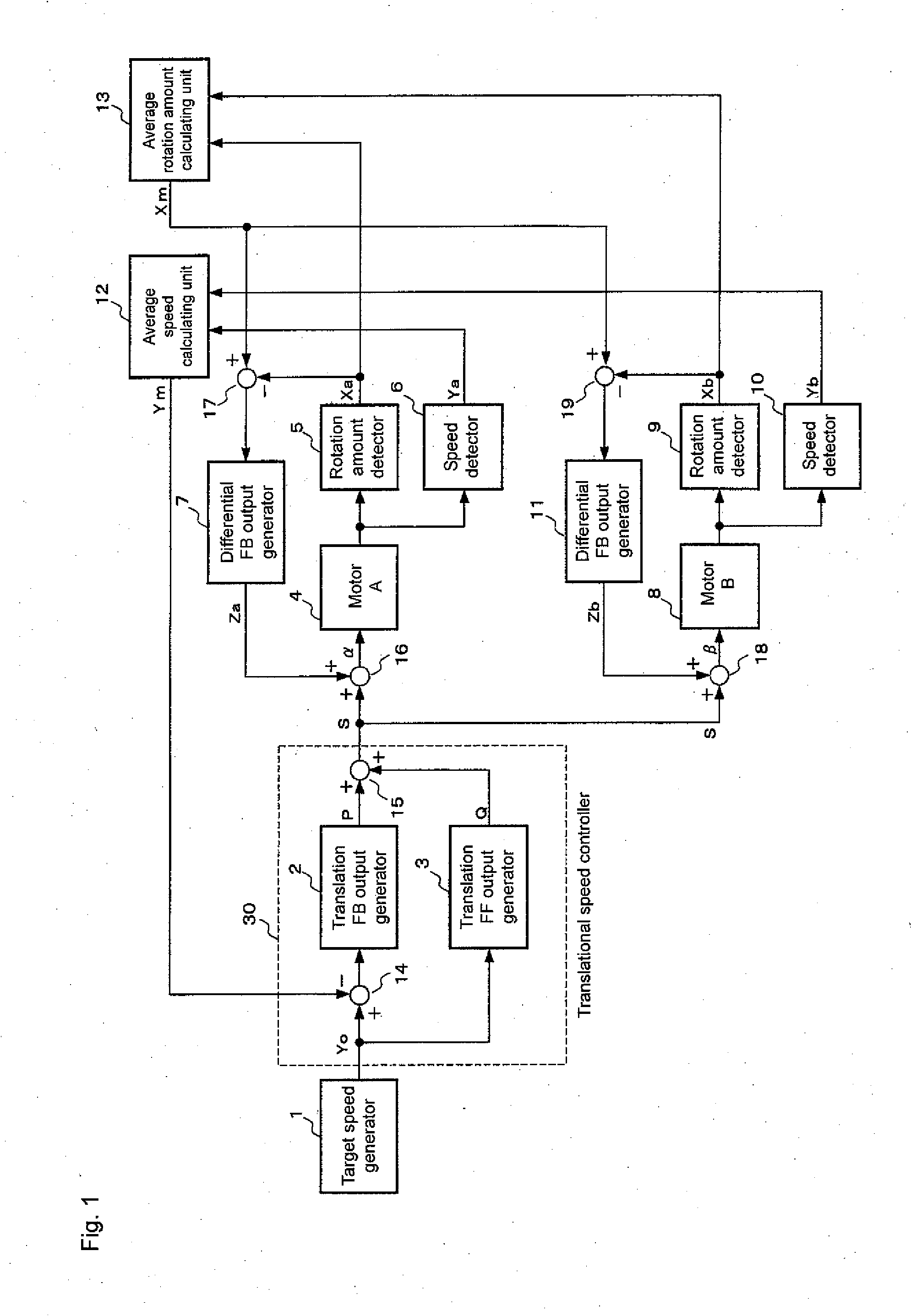
[0014]FIG. 1 shows a control block diagram of a motor control device according to one or more embodiments of the present invention. A target speed generator 1 for generating target speed (target value of rotational speed) includes a target speed table in which a target speed corresponding to a position of a movable body is set in advance. A translational speed controller 30 for controlling rotational speeds of two motors 4, 8 is configured by a translation FB (feed back) output generator 2, a translation FF (feed forward) output generator 3, a calculator 14, and a calculator 15. The translation FB output generator 2 performs control such that the rotational speeds of the motors 4, 8 become equal, and is configured by a proportional element for outputting a signal proportional to an inputted deviation, and an integrator element for outputting a signal proportional to a time integration value of the deviation. The translation FF output generator 3 includes a feed forward element for o...


PUM


Abstract

A motor control device has a target speed generating unit for generating a generated target rotational speed, speed detecting units for detecting rotational speeds of each of the plurality of motors, an average speed calculating unit for averaging the detected rotational speeds of each of the plurality of motors to calculate an average rotational speed, a drive command value output unit for outputting a drive command value to each of the plurality of motors based on the generated target rotational speed and the average rotational speed, rotation amount detecting units for detecting the rotation amounts of each of the plurality of motors, an average rotation amount calculating unit for averaging the detected rotation amounts of each of the plurality of motors to calculate an average rotation amount, and drive command value changing units for generating a feedback signal for rotation amount control corresponding to each of the plurality of motors based on the average rotation amount and the detected rotation amounts, and changing the drive command value to be provided to each of the plurality of motors from the drive command value output unit based on the feedback signal.

Description

BACKGROUND OF THE INVENTION[0001]1. Field of the Invention[0002]The present invention relates to motor control devices for performing synchronous control such that rotational speeds and rotation amounts of a plurality of motors become equal.[0003]2. Description of the Related Art[0004]In a convertible vehicle having a roof that can be freely opened and closed on the upper part of a vehicle compartment, the roof being folded and accommodated in a back trunk, a movable body such as roof and trunk is moved by rotating two motors arranged on the right and the left. However, when the rotational speeds and the rotation amounts (rotation angles) of the two motors differ due to variation in motor properties, variation in friction force of a link mechanism driven by the motors or difference in load of the motors caused by the tilt of the vehicle body, imbalanced force acts on the movable body, whereby the movable body may be deformed, or in an extreme case, broken.[0005]A control device that...

Claims


Application Information

Patent Timeline
Patent Type & Authority Applications(United States)
IPC IPC(8): H02P5/50B60J7/12
CPCH02P5/50
Inventor HAYASHI, KENSUKE
Owner OMRON AUTOMOTIVE ELECTRONICS CO LTD
Features
  • Generate Ideas
  • Intellectual Property
  • Life Sciences
  • Materials
  • Tech Scout
  • Unparalleled Data Quality
  • Higher Quality Content
  • 60% Fewer Hallucinations
Learn More