Profile inspection system for threaded and axial components

a technology of axial components and profile inspection, applied in the direction of process and machine control, program control, instruments, etc., can solve the problems of inability to cover 100% of the threaded surface during the inspection, difficulty in adjusting, and inability to wear contact feelers with us

Active Publication Date: 2008-02-28
GII ACQUISITION LLC DBA GENERAL INSPECTION
View PDF29 Cites 55 Cited by
  • Summary
  • Abstract
  • Description
  • Claims
  • Application Information

AI Technical Summary

Benefits of technology

[0015]In the preferred embodiment, the processor is further operative to record the composite profile of the component at one or more angular orientations by rotating the component through a predetermined angle about its axis. Using the composite profile of the component at one or more angular orientations, the processor may generate a three-dimensional model the component by assembling the composite profiles of the component taken at a plurality of angular orientations.

Problems solved by technology

One disadvantage of such devices is that the contact feelers can become worn with usage or become out of adjustment.
Also, because the gage only takes a reading when the feeler is contacting the component, 100% coverage of the threaded surface during the inspection is not possible.
However, the assumption must be made that the part is placed perfectly in the center relative to lens; if not, diameter measurement may be problematic.
In addition, since the resolution limit is a strong function of laser wavelength, performance may suffer if component layout is not properly aligned.
For example, if the light from the laser varies, this will result in a change at the detectors which, in turn, could be misinterpreted as a diameter irregularity.

Method used


Image

  • Profile inspection system for threaded and axial components
  • Profile inspection system for threaded and axial components
  • Profile inspection system for threaded and axial components

Examples


Embodiment Construction

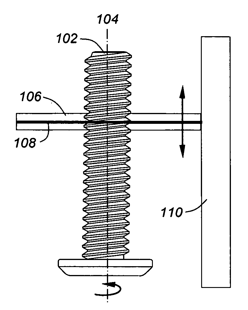
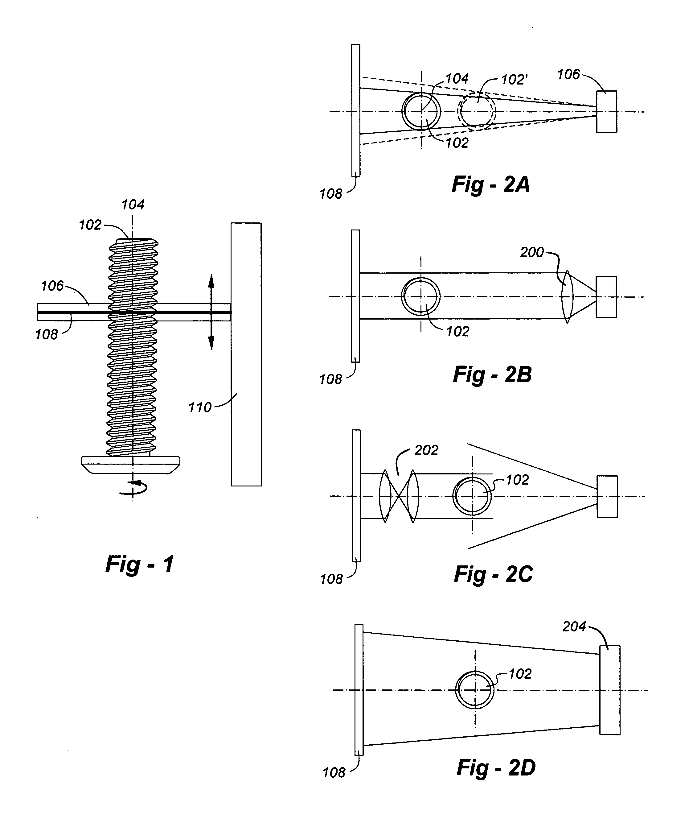
[0026]FIG. 1 is a drawing which illustrates the preferred embodiment of the invention. A part 102 to be inspected is placed in a fixture (discussed later) allowing the component to be rotated about axis 104. Behind the component 102 is a bright, horizontally oriented light source 106 and, in front of the component 102 is a horizontally oriented light detector 108. It must be kept in mind that this is a highly simplified drawing, such that details of the light source, detector and other features are not illustrated for the purposes of clarity. Nor are any of the enclosures that would be used for most of the components.

[0027]The light source 106 and detector 108 are physically coupled to one another, such that they move as a unit up and down along the axis of the part 104. This is accomplished by connecting the light source and detector to a column 110, including a translation mechanism and linear encoder for precise movement. In the preferred embodiment, the light source and detector...


PUM


Abstract

A system and method are disclosed for inspecting a component having a length, a width, and an axis. The system includes a fixture for holding the component, a light source disposed on one side of the component, and an optical detector disposed on the other side of the component. In the preferred embodiment, the detector has a field of view wider than the width of the component, thereby enabling the detector to image a portion of the outer edges of the component. A translation stage is operative to move the light source and detector in unison along the length of the component and a processor, in communication with the detector and the translation stage, is operative to: a) receive electrical signals representative of the outer profile imaged by the detector; b) move the translation stage incrementally along the length of the component; and c) record the outer profile imaged by the detector at each increment and form a composite profile of the component. In the preferred embodiment, the processor is further operative to record the composite profile of the component at one or more angular orientations by rotating the component through a predetermined angle about its axis.

Description

FIELD OF THE INVENTION[0001]This invention relates generally to component inspection and, in particular, to a system and method for inspecting the profile of threaded and cylindrical components.BACKGROUND OF THE INVENTION[0002]There is a need in many industries for the measurement of thread characteristics on screws, bolts and other fasteners and components. Apparatus for this purpose may be broadly categorized into contact and non-contact approaches. Contact-type gages typically employ feelers which contact the threaded surface to be measured at set points and mechanically measure the tolerances. One disadvantage of such devices is that the contact feelers can become worn with usage or become out of adjustment. Also, because the gage only takes a reading when the feeler is contacting the component, 100% coverage of the threaded surface during the inspection is not possible.[0003]Numerous non-contact thread measurement techniques have been developed, including systems that employ la...

Claims


Application Information

Patent Timeline
Patent Type & Authority Applications(United States)
IPC IPC(8): G01B11/24
CPCG01B11/2433G01B11/2425G05B2219/37212
Inventor CROWTHER, DAVID
Owner GII ACQUISITION LLC DBA GENERAL INSPECTION
Why Eureka
Try Eureka