Connecting element

a technology of connecting elements and elements, applied in the direction of furniture joining, writing tables, rod connections, etc., can solve the problems of time-consuming and complicated assembling of modular furniture that consists of such screw connections, and the rigidity of modular furniture joined in this manner is often insufficient for use in offices or at exhibitions, and achieves the effect of stable positioning of elements relative to each other

Inactive Publication Date: 2008-02-28
VEYHL
View PDF17 Cites 9 Cited by
  • Summary
  • Abstract
  • Description
  • Claims
  • Application Information

AI Technical Summary

Benefits of technology

[0012]If, in this arrangement, the horizontal projection on the vertical element, i.e. the projection for vertically supporting the bottom projection of the horizontal element, is formed by a bottom end of the contact body, particularly stable positioning of the elements relative to each other is possible by means of the connection element according to the invention, because only two parts, i.e. the contact body and the horizontal element, are attached to each other. In this way, any play that might be present between additional parts is avoided.
[0013]Particularly preferably, the locking means are inserted through preferably one hole vertically through the contact body and are lockable from the top. In this way it is, for example, possible to assemble a substructure of a desk or a platform without having to carry out manipulation from below on the substructure after assembly of said substructure in order to interlock the individual elements. For example, a cam lever can then simply be engaged from above in order to secure the structure. Because the locking means are inserted through the contact body, the locking means, i.e. the entire clamping element, can already be captively installed on the vertical element. In this way, there is no need to separately provide the individual parts of the clamping elements.

Problems solved by technology

Assembling modular furniture that comprises such screw connections is, however, time consuming and complicated because the screws to be used can only be screwed in after precise positioning of the elements relative to each other.
If the elements are hooked into each other this allows quick assembly of the modular furniture, however, there often remains some play between the elements that have been hooked into each other, so that modular furniture joined in this manner is often insufficiently rigid for use in offices or at exhibitions.

Method used


Image

  • Connecting element
  • Connecting element
  • Connecting element

Examples


Embodiment Construction

[0021]The figures of the drawings show the object according to the invention in a schematic manner and are not to scale. The individual components of the object according to the invention are shown such that their design is clearly evident.

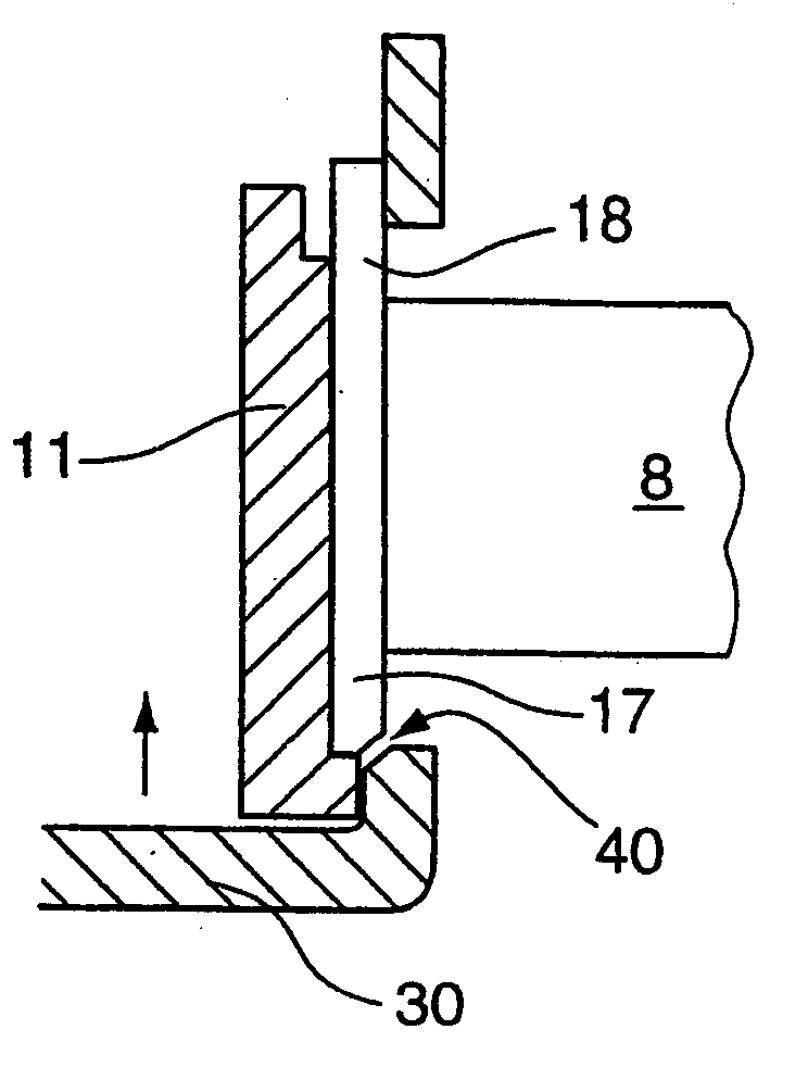
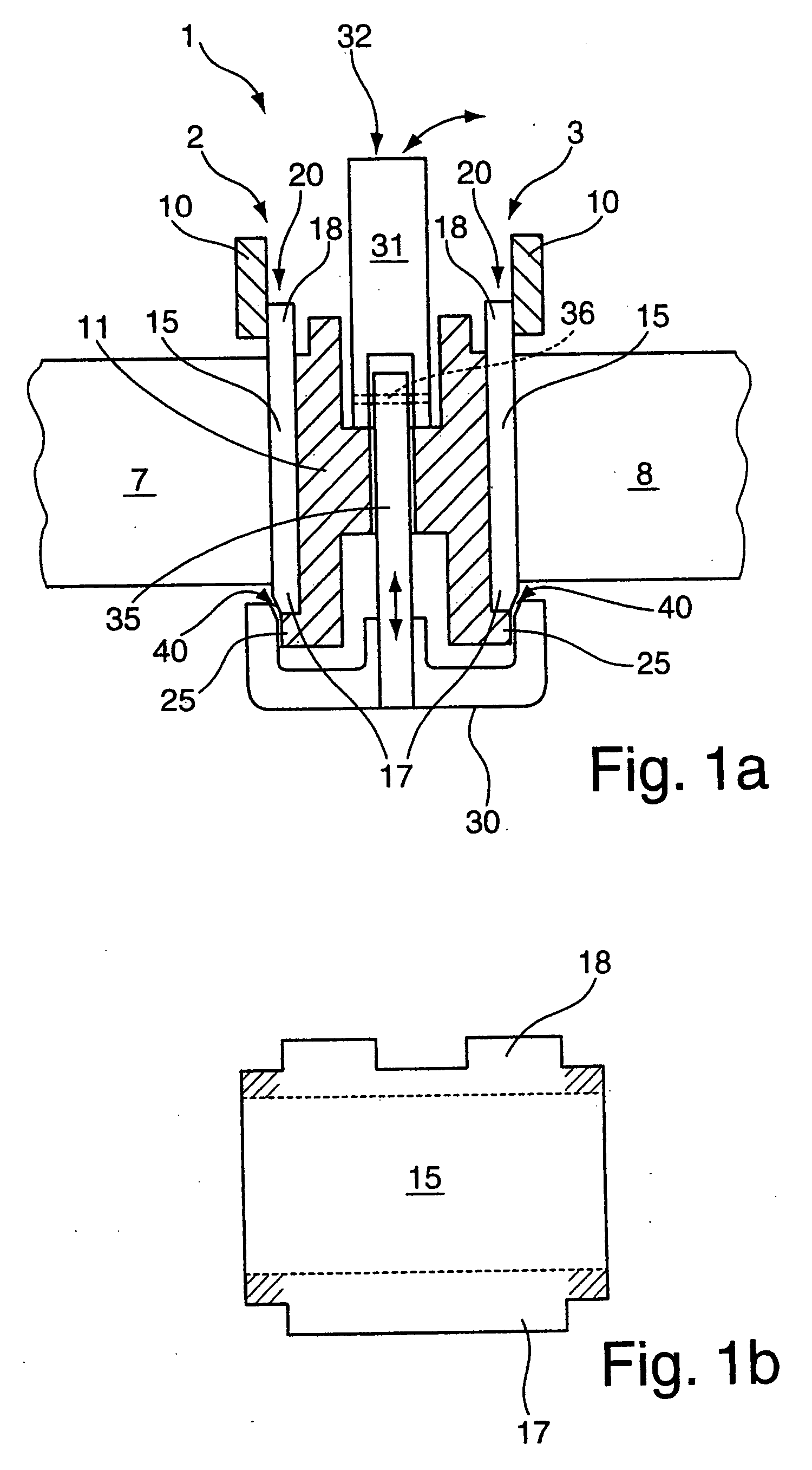
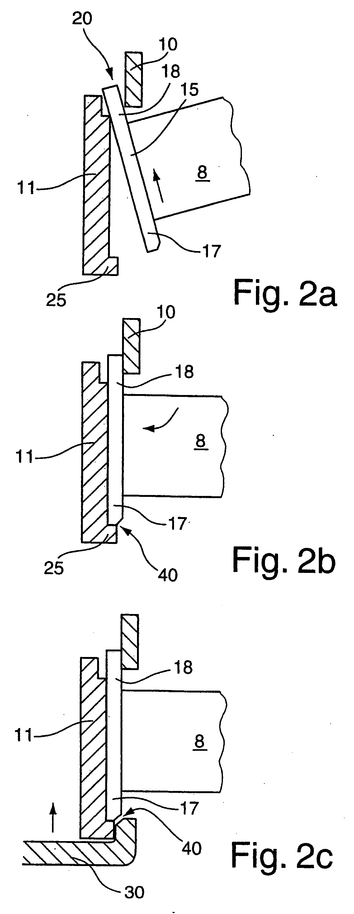
[0022]FIGS. 1 show a connection system 1 according to the invention with two connection elements 2, 3 according to the invention, the connection elements 2, 3 being arranged so as to be symmetrical relative to a mid-plane of a vertical element. In each case, a horizontal element 7, 8 is installed on the vertical element via one of the connection elements 2, 3. FIG. 1a shows a section view of the connection system 1 according to the invention which is perpendicular to the mid-plane of the vertical element. Thus, only part of the outside wall 10 and a contact body 11 of the vertical element is shown. FIG. 1b shows a top view of an adapter plate 15, welded to the free ends of the horizontal elements 7, 8. Such adapter plates 15 form top and bottom pr...


PUM


Abstract

A connection element 2, 3 for attaching a horizontal element 7, 8 to a vertical element is proposed. In this arrangement, a free end of the horizontal element 7, 8 comprises at least one top projection 18 and at least one bottom projection 17; and on the vertical element 56 at least one hooking-in aperture 20 for accommodating the top projection 18 of the horizontal element 7, 8 and at least one horizontal projection 25 for the vertical support of the bottom projection 17 of the horizontal element 7, 8 are provided, wherein a clamping element 30 with locking means 32 is provided for horizontal securing of the bottom projection 17 of the horizontal element 7, 8.

Description

[0001]This application claims Paris Convention priority of DE 10 2006 039 569.7 filed Aug. 23, 2006 the complete disclosure of which is hereby incorporated by reference.BACKGROUND OF THE INVENTION[0002]The invention relates to a connection element, preferably in modular furniture elements, for attaching a horizontal element to a vertical element. Such connection elements are, for example, provided on modular furniture desks or tables, e.g. office desks, wherein the vertical element is formed by a desk leg while the horizontal element is formed by a longitudinal support that stabilises the modular furniture desk. Such connection elements are, for example, known from the printed publications EP 0 594 939 B1, EP 0 087 498 B1, EP 0 065 036 B1 and EP 0 164 041 B1.[0003]In known connection elements, the elements to be arranged horizontally (horizontal elements) are usually screwed to or hooked to the elements to be arranged vertically (vertical elements). When the elements are screwed tog...

Claims


Application Information

Patent Timeline
Patent Type & Authority Applications(United States)
IPC IPC(8): A47B13/02F16B12/48
CPCA47B13/06A47B17/003Y10T403/32254F16B12/40A47B2200/0013
Inventor BRUDER, WOLFGANGSCHOBER, HORST
Owner VEYHL
Why Eureka
Try Eureka