Turbine blade with split impingement rib

a turbine blade and impingement rib technology, applied in the direction of machines/engines, sustainable transportation, mechanical equipment, etc., can solve the problems of high stress on the impingement rib, and achieve the effect of reducing local stress concentration and balanced stress distribution

Inactive Publication Date: 2008-02-28
RAYTHEON TECH CORP
View PDF7 Cites 27 Cited by
  • Summary
  • Abstract
  • Description
  • Claims
  • Application Information

AI Technical Summary

Benefits of technology

[0007]The paddles provide a gradual transition from the relatively stiff solid rib to no rib, and allow for a balanced distribution of stress. Further, splitting the rib has only a minor effect on internal flow characteristics, such that the function of the impingement rib of metering flow is still achieved.
[0008]In addition, in a disclosed embodiment, several of the pedestals near the airfoil to platform interface are formed to not extend completely between the two walls. Instead, pedestal stubs extend from each of the wall towards the other but are spaced in the center. Again, this reduces local stress concentration.

Problems solved by technology

One challenge with the prior art turbine blades is that there are high stresses on the impingement rib, in particular at an area adjacent to the platform.

Method used


Image

  • Turbine blade with split impingement rib
  • Turbine blade with split impingement rib
  • Turbine blade with split impingement rib

Examples


Embodiment Construction

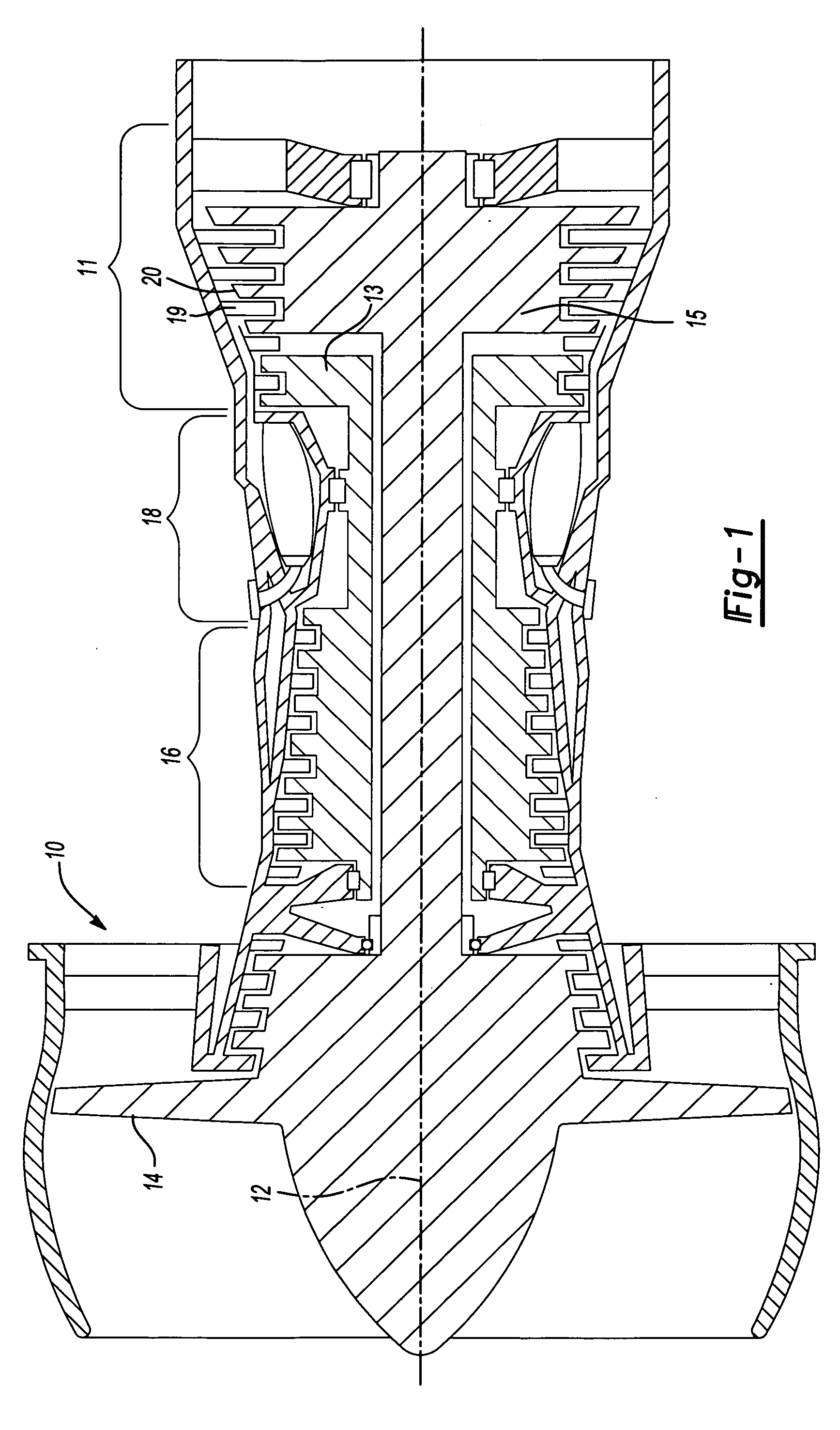
[0015]FIG. 1 shows a gas turbine engine 10, such as a gas turbine used for power generation or propulsion, circumferentially disposed about an engine centerline, or axial centerline axis 12. The engine 10 includes a fan 14, a compressor 16, a combustion section 18 and a turbine 11. As is well known in the art, air compressed in the compressor 16 is mixed with fuel that is burned in the combustion section 18 and expanded in turbine 11. The air compressed in the compressor and the fuel mixture expanded in the turbine 11 can both be referred to as a hot gas stream flow. The turbine 11 includes rotors 13 and 15 that, in response to the expansion, rotate, driving the compressor 16 and fan 14. The turbine 11 comprises alternating rows of rotary blades 20 and static airfoils or vanes 19. FIG. 1 is a somewhat schematic representation, for illustrative purposes only, and is not a limitation on the instant invention that may be employed on gas turbines used for electrical power generation, ai...


PUM


Abstract

A gas turbine engine is provided with an airfoil component that is disclosed as a turbine blade. Internal cooling passages circulate air within the blade. An impingement rib separates a cooling air channel from a pedestal array, and includes cross-over holes to meter the flow of air into the pedestal array. A lower end of the impingement rib is split to reduce stress concentrations between the impingement rib and a platform. Further, the pedestals adjacent to the lower end of the impingement rib are formed to be stubs, which do not extend entirely across a width of the blade. The disclosed structure reduces the stress concentration at an area where the impingement rib meets the platform.

Description

BACKGROUND OF THE INVENTION[0001]This application relates to an internally cooled turbine blade for use in a gas turbine engine, wherein an impingement rib which meters flow of air into a pedestal array has a split lower portion.[0002]Gas turbine engines are known, and include a plurality of sections, typically serially connected. A fan section supplies air to a compressor section. The compressor section compresses the air and delivers it to a combustion section. The combustion section combusts the air with a mixed fuel, and passes the products of combustion downstream over turbine rotors. The turbine rotors are driven to rotate, and in turn create power, and rotate the fan and compressor sections.[0003]Typically, the turbine section includes a plurality of rotors each mounting a plurality of blades. The blades are exposed to relatively high temperature from the products of combustion. Thus, it is known to provide cooling air internally within the blades.[0004]Each turbine blade typ...

Claims


Application Information

Patent Timeline
Patent Type & Authority Applications(United States)
IPC IPC(8): F01D5/18
CPCF01D5/187F05D2260/22141F05D2260/201Y02T50/676Y02T50/60
Inventor CHEROLIS, ANTHONY P.PAGE, RICHARD H.
Owner RAYTHEON TECH CORP
Why Eureka
Try Eureka