Control device, handover control method and mobile communication system

a control device and control method technology, applied in the direction of electrical equipment, network topologies, data switching by path configuration, etc., can solve problems such as packet loss, and achieve the effect of favorable accuracy

Inactive Publication Date: 2008-02-28
NTT DOCOMO INC
View PDF6 Cites 0 Cited by
  • Summary
  • Abstract
  • Description
  • Claims
  • Application Information

AI Technical Summary

Benefits of technology

[0027] velocity tracking means of the control device desirably tracks, based on a plurality of combinations of the switching time difference t and the distance x between the access interfaces for the adjacent switchings, a direction which links the two access interfaces and where the first-switched access interface lies foremost as the direction of movement, and a value obtained by dividing the distance x by the switching time difference t as the velocity, with respect to each combination; and finds the vector sum of the velocity vectors for each combination and tracks the direction of movement and velocity of the mobile host and moving network by means of the vector sum thus obtained. In this case, the direction of movement and velocity pertaining to the mobile host and moving network, can be tracked with favorable accuracy.

Problems solved by technology

However, conventionally, because a variation in the communication quality of a line connected to each access interface has not been predicted, the handover that pertains to the connection to the core network at the access interface, has been performed after one line is disconnected.
Such handover is not performed smoothly and a handover latency occurs, resulting in packet loss.

Method used


Image

  • Control device, handover control method and mobile communication system
  • Control device, handover control method and mobile communication system
  • Control device, handover control method and mobile communication system

Examples


first embodiment

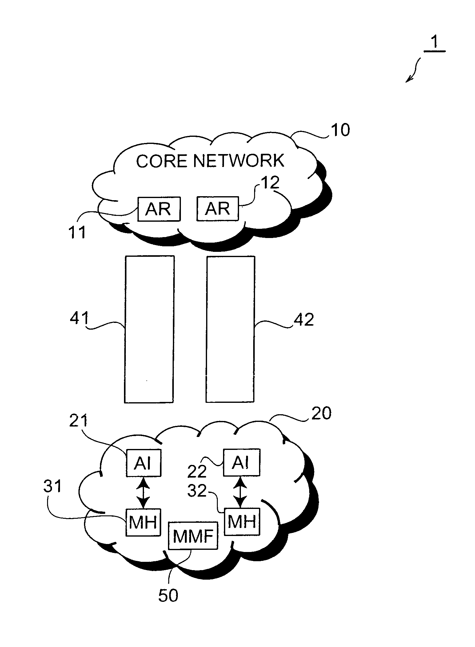
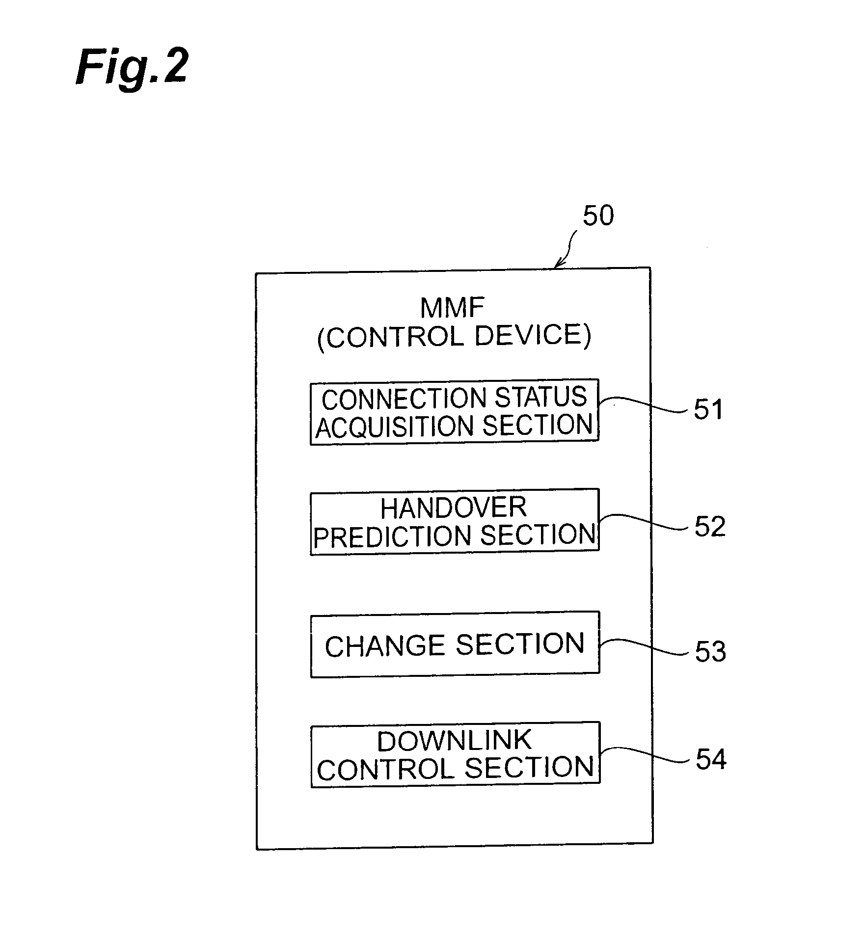
[0047]FIG. 1 is a constitutional view of a mobile communication system of a first embodiment. As shown in this figure, a mobile communication system 1 is constituted by a core network 10, which is constituted comprising a plurality of access routers (referred to as “AR” hereinafter) 11, 12; and a moving network (referred to as “MN” hereinafter) 20, which is constituted comprising a plurality of access interfaces (referred to as “AI” hereinafter) 21, 22, a plurality of mobile hosts (referred to as “MH” hereinafter) 31, 32, and a control device (referred to as “MMF” hereinafter) 50 that is provided with a function for governing mobile management and switching instructions (MMF: Mobility Management Function). The MH 31 is connected to an AR (AR 11 in the example in FIG. 1) on the side of the core network 10 via either line 41 of the AI 21 or line 42 of the AI 22 (line 41 in the example in FIG. 1), and thus transmits and receives data. The same is true of the MH 32.

[0048] Further, the ...

second embodiment

[0063]FIG. 8 is a constitutional view of the initial state of a mobile communication system 1S of the second embodiment. As shown in this figure, a mobile communication system 1S is constituted by the core network 10, which is constituted comprising a plurality of AR 11, 12; and the MN 20, which is constituted comprising a plurality of AI 21, 22, the MH 31, and a control device (MMF) 50 that is provided with a function for governing mobile management and switching instructions (MMF: Mobility Management Function). The MH 31 is connected to either AR on the side of the core network 10 via either line 41 of the AI 21 or line 42 of the AI 22, and thus transmits and receives data.

[0064] Further, the MN 20 moves from left to right in FIG. 8. Of the two AI 21, 22, the AI 22 that lies foremost in the direction of movement is called an NAI (New Access Interface), and the AI 21 that lies rearward in the direction of movement is called an OAI (Old Access Interface). The MN 20 is therefore a m...


PUM


Abstract

An object of the present invention is to avoid packet loss and implement a seamless handover by minimizing the handover latency when a handover is implemented by a multihomed moving network (MN) or a mobile host (MH). The present invention is a mobile communication system that is constituted comprising an MN, a plurality of AI each constituting an interface for the connection to a core network at the MN, and a control device (MMF), wherein the MMF dynamically changes the AI adopted as the connection interface when a predetermined condition is satisfied on the basis of the connection status to the core network at each AI or the prediction information for a subsequent handover. In so doing, the control device continues the transmission and receipt of data with respect to an appropriate AI capable of maintaining a predetermined communication quality, and maintains the connection to the core network of another AI while causing this AI to enter a closed state in which the transmission and receipt of data is disabled.

Description

CROSS-REFERENCE TO RELATED APPLICATIONS [0001] This application is a continuation of and is based upon and claims the benefit of priority under 35 U.S.C. §120 for U.S. Ser. No. 10 / 690,524, filed Oct. 23, 2003, and claims the benefit of priority under 35 U.S.C. § 119 from Japanese Patent Application No. 2002-313092, filed Oct. 28, 2002, the entire contents of each which are incorporated herein by reference.BACKGROUND OF THE INVENTION [0002] 1. Field of the Invention [0003] The present invention relates to control device, handover control method and mobile communication system, and more particularly, to handover control method by a mobile communication system constituted comprising a mobile host, or a moving network comprising a plurality of mobile hosts; a plurality of mutually connectable access interfaces each constituting an interface for the connection to a core network at the mobile host or moving network; and a control device for controlling a handover relating to the connectio...

Claims


Application Information

Patent Timeline
Patent Type & Authority Applications(United States)
IPC IPC(8): H04Q7/20H04L12/28H04W36/08H04W36/30H04W36/32H04W36/34H04W36/38H04W40/08H04W84/12H04W88/08
CPCH04L47/10H04W84/005H04W36/32H04W36/24
Inventor SUZUKI, TOSHIHIROKAWAKAMI, HIROSHIOKURA, AKIHITOYABUSAKI, MASAMI
Owner NTT DOCOMO INC
Why Eureka
Try Eureka