Caged floating seal assembly

a floating seal and assembly technology, applied in the field of sealing assemblies, can solve the problems of not usually preventing the escaping of gas, limited effective dimensional range, and disruption of the performance of surgery, and achieve the effect of facilitating the disposition of sealed segments

Active Publication Date: 2008-02-28
TELEFLEX MEDICAL INC
View PDF69 Cites 115 Cited by
  • Summary
  • Abstract
  • Description
  • Claims
  • Application Information

AI Technical Summary

Benefits of technology

[0015]In accordance with another embodiment of the present invention, a seal assembly is provided for sealing engagement with differently dimensioned instruments passing through a trocar. A caged seal assembly includes a plurality of caged segments movably connected to one another. The caged seal assembly includes a plurality of seal segments each connected to a different one of said cage segments and movable therewith between a sealing orientation and a non sealing orientation relative to an instrument passing through said caged seal assembly. A biasing assembly is connected to said cage segme

Problems solved by technology

However, these types of seals will not usually prevent the escaping of gas once a medical instrument has been removed from the trocar.
This fact, however, presents an obstacle for preventing the escape of gas by a septum-type valve because such valves typically accommodate and effectively seal against medical instruments having a comparatively small and relatively limited range of outer diameters.
This limited effective dimensional range may cause some disruption in the performance of the surgery.
For example, the septum valve seal will not perform adequately when a medical instrument having a smaller outer diameter than the set size offered by the septum valve must be used.
During such an occurrence there is a strong possibility that some insufflation gas will escape thereby necessitating the abdominal cavity being inflated again.
As another example, if a medical instrument having a much larger outer diameter which is beyond the size of the valve within the trocar, there may be an unacceptable drag or friction force exerted on the instrument during its

Method used


Image

  • Caged floating seal assembly
  • Caged floating seal assembly
  • Caged floating seal assembly

Examples


Embodiment Construction

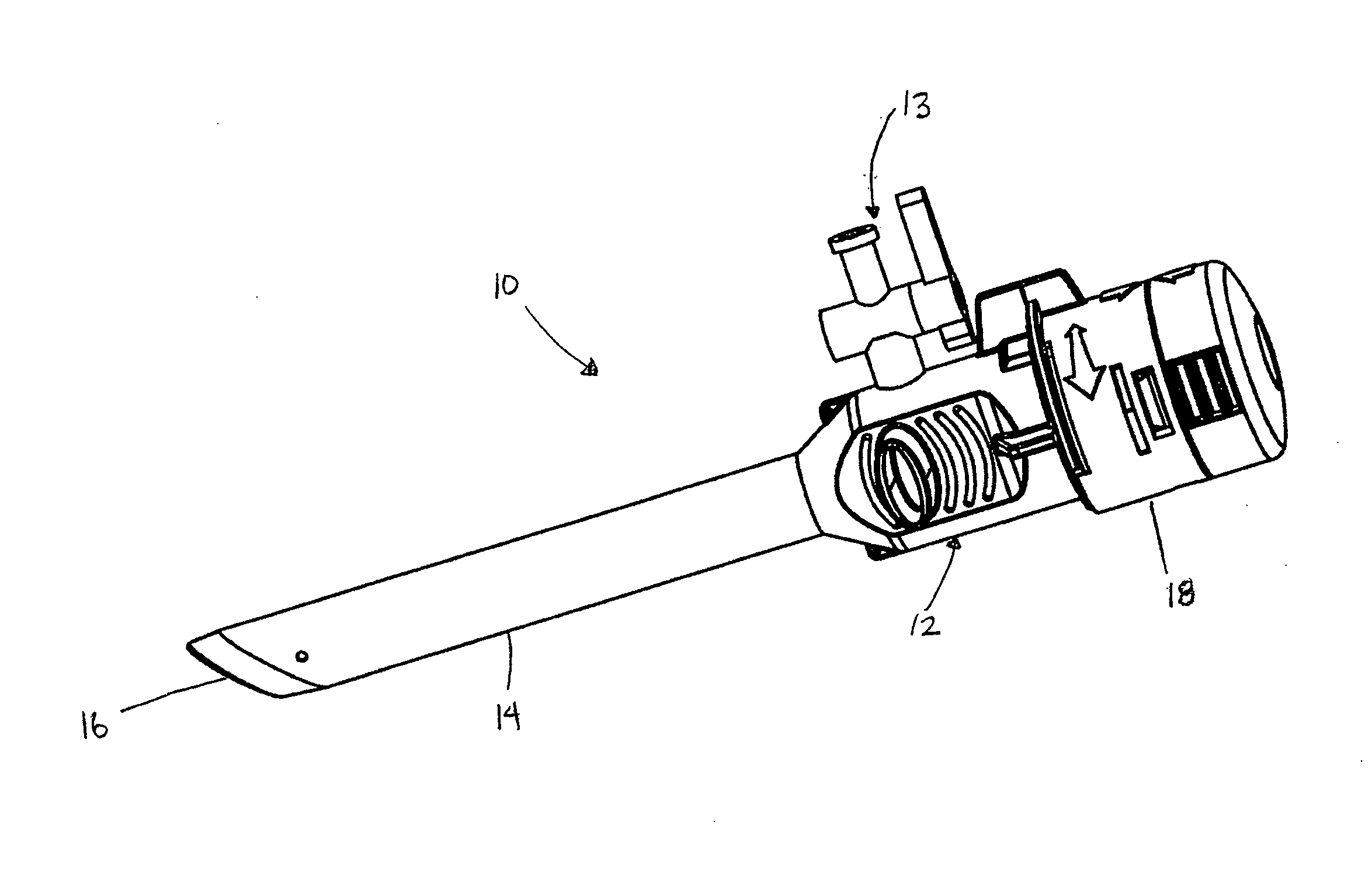
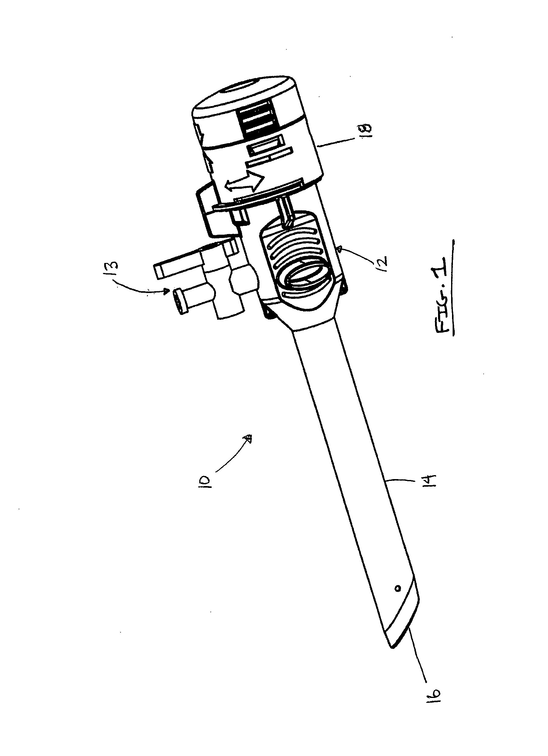
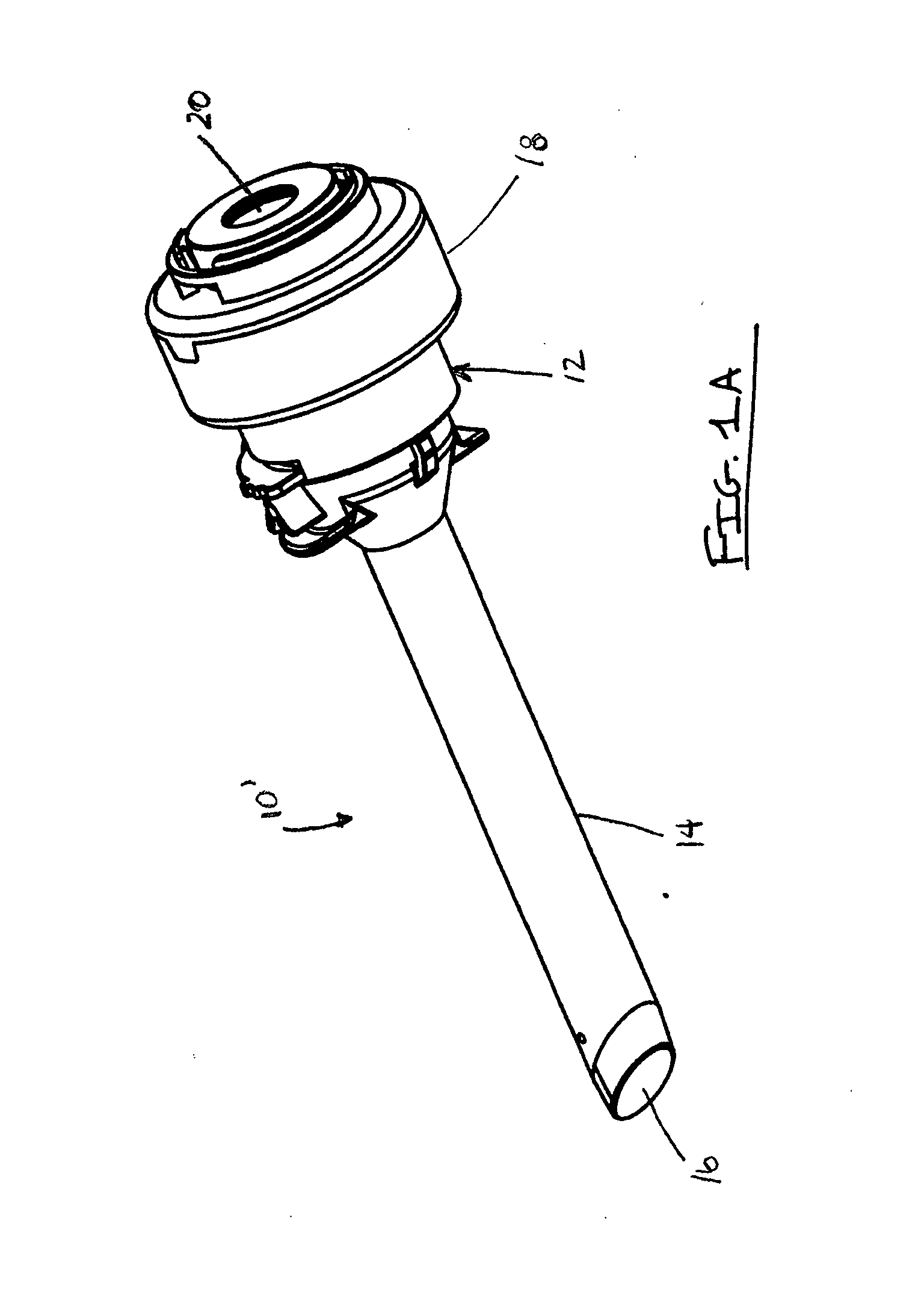
[0041]The present invention is intended to present a solution to these and other long felt needs in this field of art, and as such, relates to a seal assembly including a caged seal assembly primarily structured to be used with a trocar or like device. The caged seal assembly is operational independent of, but preferably in combination with, an additional seal assembly, also defining a preferred embodiment of the present invention, and disposed along a common instrument path within the trocar. As such, the combined caged seal assembly and the additional seal assembly facilitates the sealed passage of medical instruments through the trocar, so as to prevent the escape of insufflation gas such as during laparoscopic surgery. The seal assembly of the present invention is directed to what is accurately and descriptively referred to herein as a movable or “floating” and / or “caged” seal assembly, the features of which are discussed in detail hereinafter.

[0042]More specifically, the variou...


PUM


Abstract

A seal assembly establishes sealing engagement with a plurality of differently dimensioned instruments passing through a trocar. The seal assembly is a caged seal assembly movably disposed within the trocar and includes at least two seal segments disposable into and out of a sealing orientation relative to the instrument. A cage structure of the seal assembly includes at least two cage segments each connected to a seal segment, a biasing assembly connected to the cage structure and disposed and structured to normally bias the seal segments into sealing orientation.

Description

CROSS-REFERENCE TO RELATED APPLICATIONS[0001]This application claims priority to U.S. provisional patent application No. 60 / 840,174, filed Aug. 25, 2006, and U.S. provisional patent application No. 60 / 852,583, filed Oct. 18, 2006, the disclosure of each of which is hereby incorporated by reference in its entirety.FIELD OF THE INVENTION[0002]The present invention relates generally to medical devices. More particularly, the present invention relates to seal assemblies for trocars and like instruments.BACKGROUND OF THE INVENTION[0003]This invention relates to a caged seal assembly that is floatingly movable within a trocar or like device and intended for use independently of, but preferably, in combination with another seal assembly, which is also floatingly movable within the trocar. As such, a variety of medical instruments can be utilized with the present invention, so as to introduce and / or access the body cavity of a patient, regardless of the fact that each instrument may have a ...

Claims


Application Information

Patent Timeline
IPC IPC(8): A61M31/00
CPCA61B17/3462A61B2017/3464A61B2017/00876A61M39/0613A61M2039/0626A61M2039/0653A61M2039/0686
Inventor MCFARLANE, RICHARD H.
Owner TELEFLEX MEDICAL INC
Why Eureka
Try Eureka