System and method for adjusting the thickness of a prosthesis

a prosthesis and thickness technology, applied in the field of system and method for adjusting the thickness of the prosthesis, can solve the problems of inability to easily re-sterilize, thicker tibial inserts are associated with higher wear, and the implants are usually associated with a long shelf aging da

Inactive Publication Date: 2008-02-28
EXACTECH INC
View PDF9 Cites 106 Cited by
  • Summary
  • Abstract
  • Description
  • Claims
  • Application Information

AI Technical Summary

Problems solved by technology

As a result, these implants are usually associated with a long shelf aging date at the time of the surgery, assuming the part is ever used.
Consequently, the thicker tibial inserts could be associated with higher wear.
Because the implants manufactured from UHMWPE cannot be easily re-sterilized, the returned implants typically represent a loss for the company.
Moreover, a thick tibial insert is often associated with loss of proximal tibia bone.

Method used


Image

  • System and method for adjusting the thickness of a prosthesis
  • System and method for adjusting the thickness of a prosthesis
  • System and method for adjusting the thickness of a prosthesis

Examples


Embodiment Construction

[0037] Detailed embodiments of the present invention are disclosed herein; however, it is to be understood that the disclosed embodiments are merely illustrative of the invention that may be embodied in various forms. In addition, each of the examples given in connection with the various embodiments of the invention is intended to be illustrative, and not restrictive. Further, the figures are not necessarily to scale, some features may be exaggerated to show details of particular components. Therefore, specific structural and functional details disclosed herein are not to be interpreted as limiting, but merely as a representative basis for teaching one skilled in the art to variously employ the present invention.

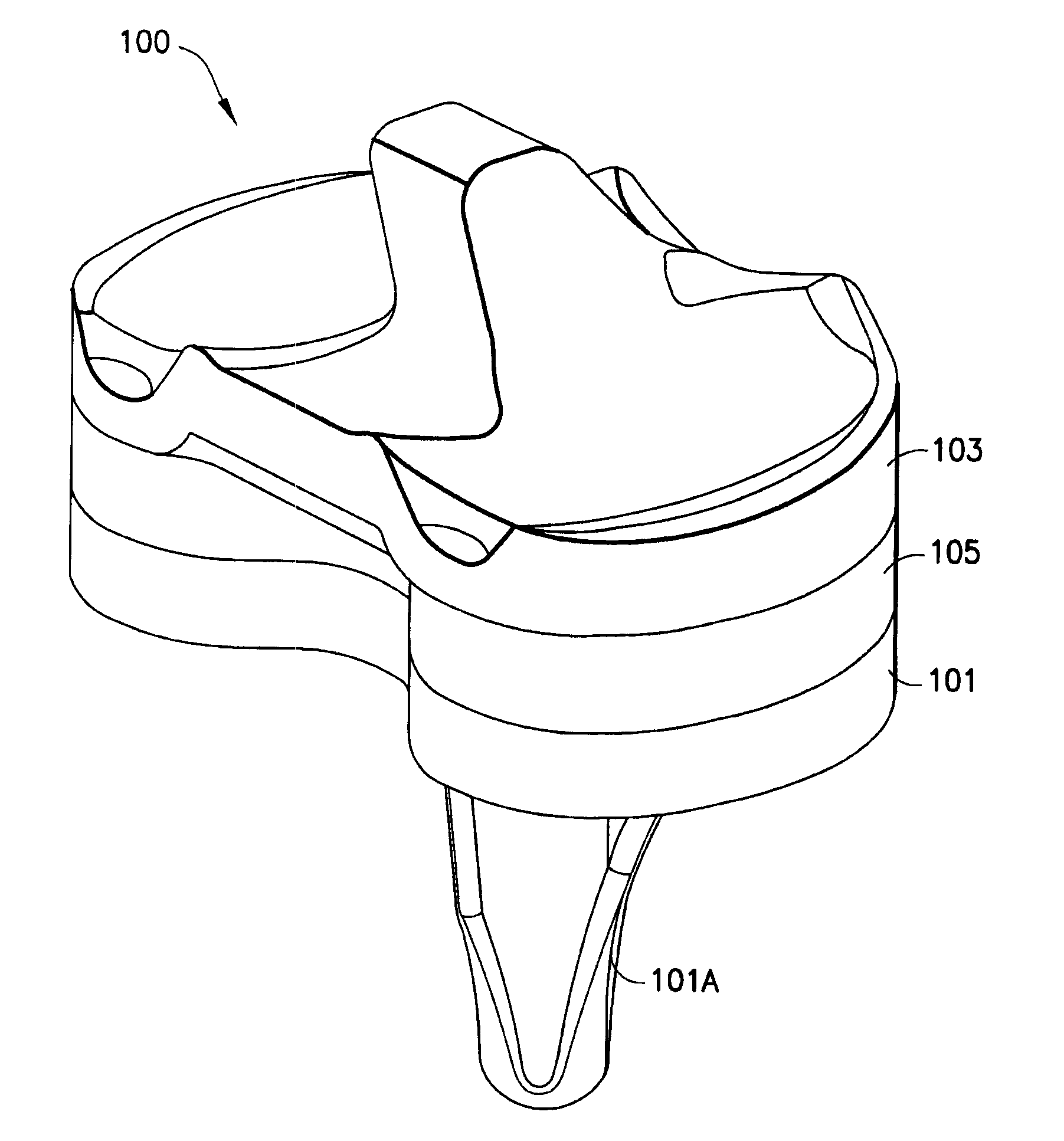
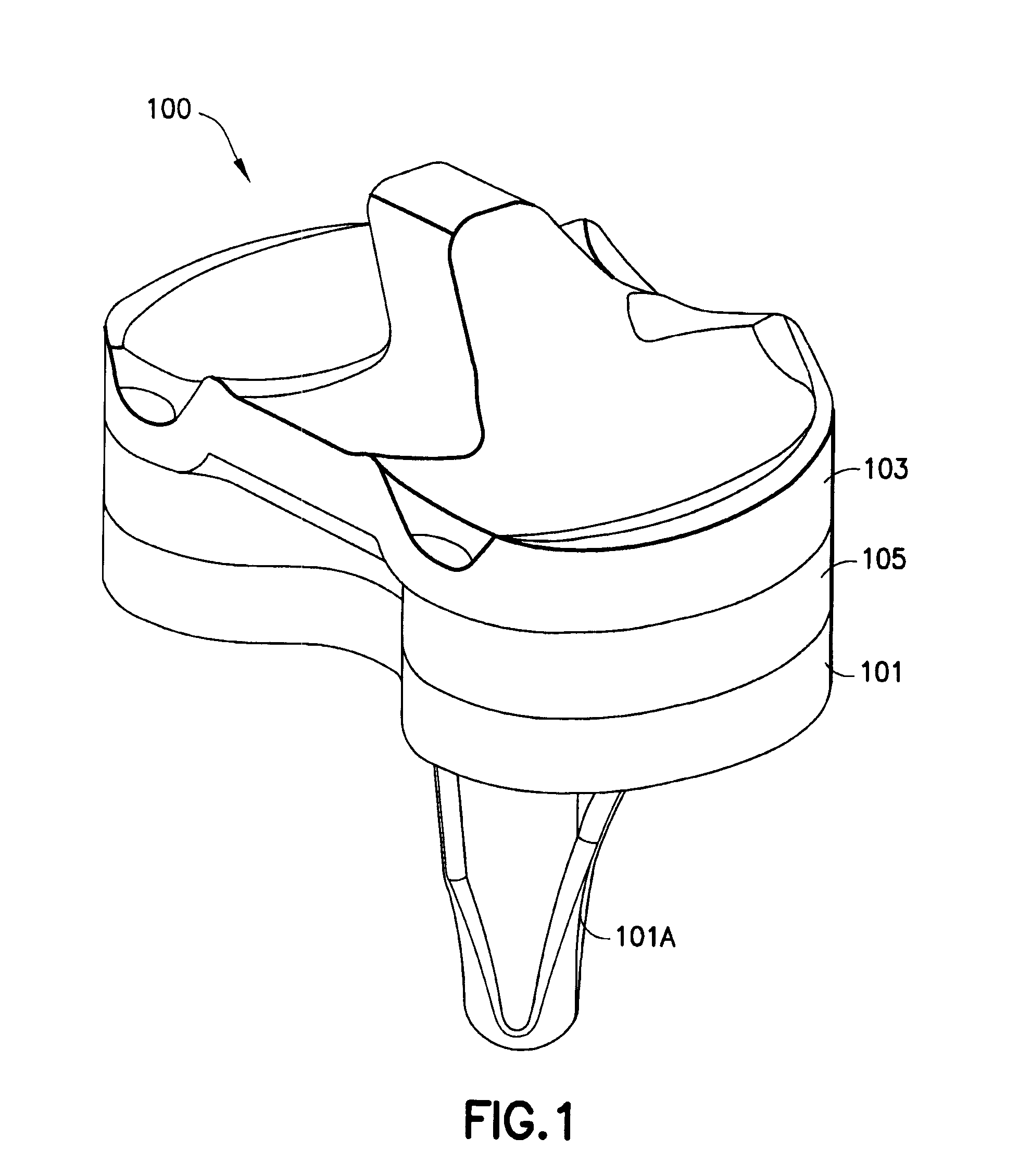
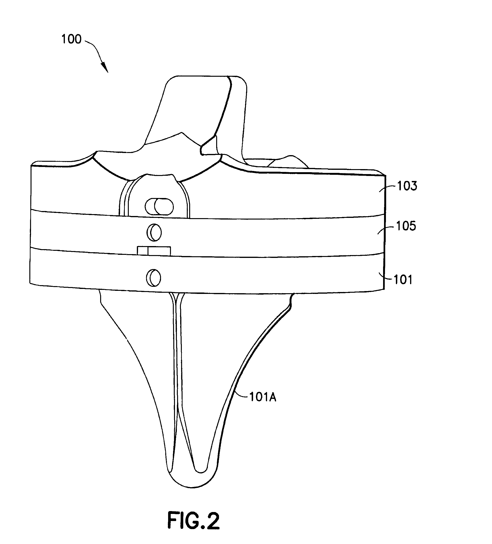
[0038] In one embodiment, instead of using a thick tibial insert in the case of a large gap between the resected tibia and femur, the composite tibial thickness (i.e. thickness of the tibial tray and tibial insert) may be adjusted using a tibial spacer between the tibial tr...


PUM


Abstract

The present invention relates to a system and method for adjusting a thickness of a prosthesis (e.g., a knee implant). In one embodiment, a knee prosthesis for implantation in a patient is provided, comprising: a tibial tray, wherein the tibial tray comprises an upper surface and a lower surface, and the lower surface of the tibial tray is disposed adjacent a tibia of the patient; a tibial insert, wherein the tibial insert comprises an upper surface and a lower surface; a tibial spacer, wherein the tibial spacer comprises an upper surface and a lower surface, and wherein the tibial spacer is disposed between the tibial tray and the tibial insert such that the lower surface of the tibial spacer is adjacent the upper surface of the tibial tray and the upper surface of the tibial spacer is adjacent the lower surface of the tibial insert; and at least one locking mechanism, wherein the locking mechanism locks the tibial spacer to the tibial tray to form a locked spacer / tray assembly such that the locking mechanism substantially prohibits at least relative up-down movement between the tibial spacer and the tibial tray when the locked spacer / tray assembly is implanted in the patient. In one example, the locking mechanism may further lock the tibial spacer to the tibial insert to form a locked insert / spacer / tray assembly such that the locking mechanism substantially prohibits at least relative up-down movement between the tibial spacer and the tibial insert when the locked insert / spacer / tray assembly is implanted in the patient. In another embodiment, a method for implanting a knee prosthesis in a patient is provided, comprising: providing a tibial tray, wherein the tibial tray comprises an upper surface and a lower surface, and the lower surface of the tibial tray is disposed adjacent a tibia of the patient; providing a tibial insert which has a shelf life and which is not readily re-sterilizable after the shelf life has expired, wherein the tibial insert comprises an upper surface and a lower surface; and providing a tibial spacer which has a shelf life and which is re-sterilizable after the shelf life has expired, wherein the tibial spacer comprises an upper surface and a lower surface, and wherein the tibial spacer is disposed between the tibial tray and the tibial insert such that the lower surface of the tibial spacer is adjacent the upper surface of the tibial tray and the upper surface of the tibial spacer is adjacent the lower surface of the tibial insert.

Description

RELATED APPLICATIONS [0001] This application claims the benefit of U.S. Provisional Application Ser. No. 60 / 823,186, filed Aug. 22, 2006, which is incorporated herein by reference in its entirety.FIELD OF THE INVENTION [0002] The present invention relates to a system and method for adjusting a thickness of a prosthesis (e.g., a knee implant). [0003] In one embodiment, a knee prosthesis for implantation in a patient is provided, comprising: a tibial tray, wherein the tibial tray comprises an upper surface and a lower surface, and the lower surface of the tibial tray is disposed adjacent a tibia of the patient; a tibial insert, wherein the tibial insert comprises an upper surface and a lower surface; a tibial spacer, wherein the tibial spacer comprises an upper surface and a lower surface, and wherein the tibial spacer is disposed between the tibial tray and the tibial insert such that the lower surface of the tibial spacer is adjacent the upper surface of the tibial tray and the uppe...

Claims


Application Information

Patent Timeline
Patent Type & Authority Applications(United States)
IPC IPC(8): A61F2/38
CPCA61F2/30734A61F2/3886A61F2002/30616A61F2002/305A61F2002/30604A61F2/389
Inventor ANGIBAUD, LAURENTSEIDEL, ALAN
Owner EXACTECH INC
Why Eureka
Try Eureka