USB interface control panel on-line update method

a technology of usb interface control panel and update method, which is applied in the field of online update method, can solve the problems of not being able to meet the requirements of on-line update function, affecting the ability of cpu configuration, and posing a greater difficulty in on-line updating of complex programmable logic device (cpld), so as to improve the capability of configuring cpu

Inactive Publication Date: 2008-02-28
SHENZHEN MINDRAY BIO MEDICAL ELECTRONICS CO LTD
View PDF6 Cites 25 Cited by
  • Summary
  • Abstract
  • Description
  • Claims
  • Application Information

AI Technical Summary

Benefits of technology

[0012]By employing the above solutions, the present invention makes it possible to use a USB interface to realize the on-line updating of the control panel in the medical equipment and the like, so that the control panel is capable of completely updating the embedded soft-core processor firmwares and / or FPGA configuration files under the control of the host computer without any interference to the normal operation by users. The present invention is not only capable of updating the application program that controls the performance of CPU, but also capable of improving the capability of configuring the CPU and the corresponding external controllers thereof, that is, the present invention is capable of updating the CPU and the configurations of its external equipments, and altering various characteristics of the hardware of the CPU, as needed.

Problems solved by technology

At present, most of the USB interface control panels in the medical equipment are assembled by various USB interface input devices such as keyboards that use commercial USB interface, and generally do not support on-line update function.
Accordingly, the disadvantage in prior art is that the on-line update function is not perfect.
Unfortunately, a greater difficulty is posed to the on-line updating of the Complex Programmable Logic Device (CPLD), and the realization thereof on MCU demands many resources.

Method used


Image

  • USB interface control panel on-line update method
  • USB interface control panel on-line update method
  • USB interface control panel on-line update method

Examples


Embodiment Construction

[0018]The present invention is now described in further details with reference to particular embodiments as well as the accompanying drawings.

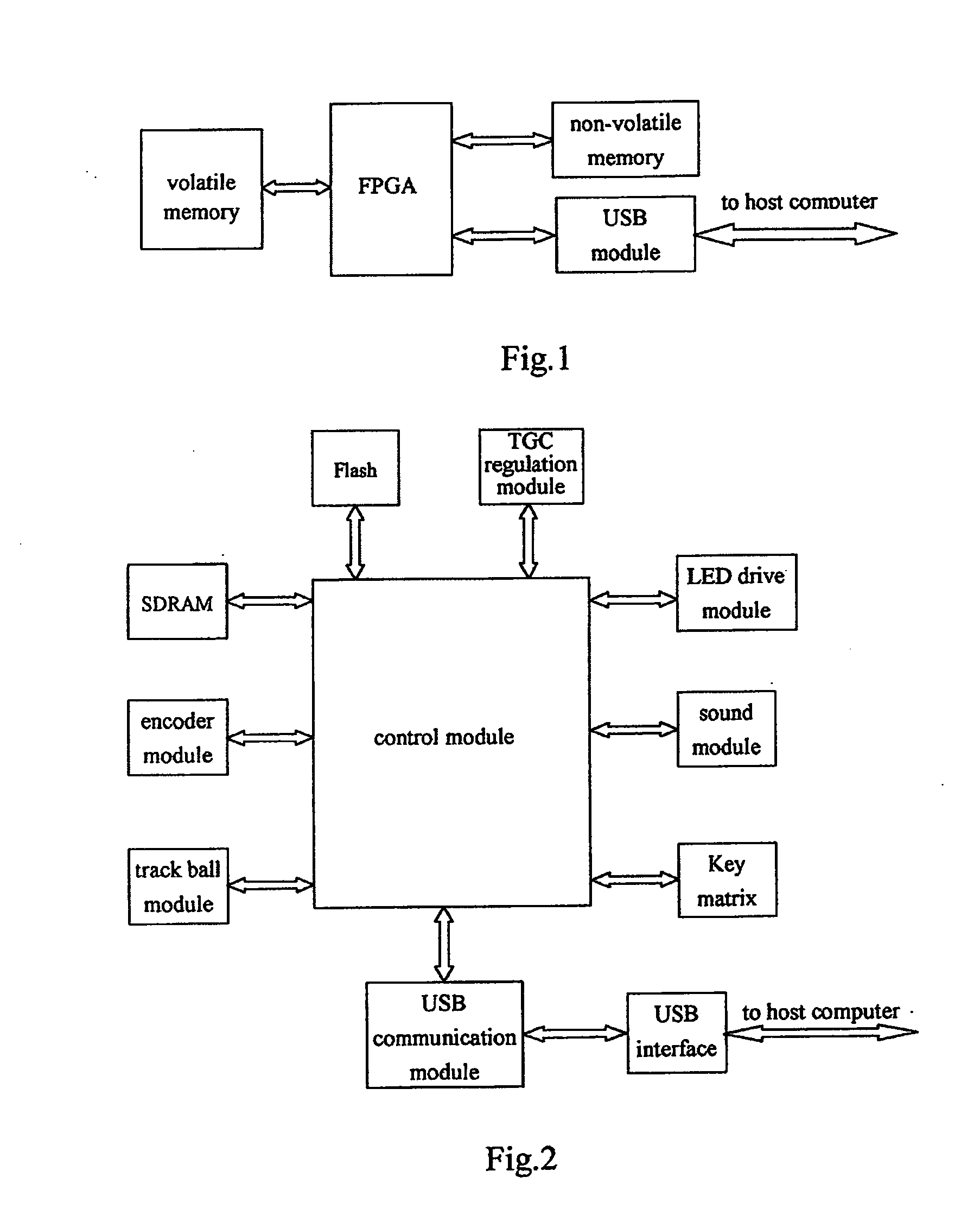
[0019]With reference to FIG. 1, the hardware construction according to the present invention generally includes FPGA, non-volatile memory, volatile memory and USB module. Wherein the FPGA as a core portion serves to realize the following logic circuits: SDRAM controller, embedded soft-core processor and other logic circuits; the non-volatile memory stores FPGA configuration files and the embedded soft-core processor firmwares, capable of long-term data preservation even in the case of power-failure; the volatile memory is used as a memory space in the embedded soft-core processor, wherein the firmwares of the embedded soft-core processor is executed after being loaded into the volatile memory, so as to enhance the execution efficiency of the embedded soft-core processor; the USB module is used to bridge the FPGA and the host computer to carry ...


PUM


Abstract

The present invention relates to a USB interface control panel on-line update method, comprising steps of: the embedded soft-core processor, after receiving through USB module the on-line update command from the host computer, receiving update data sent from the host computer, and storing the update data into the volatile memory of the embedded soft-core processor; erasing the original embedded soft-core processor firmwares and/or FPGA configuration files stored in the non-volatile memory; writing the update data stored in the volatile memory into the non-volatile memory by means of programming. The present invention uses USB interface to realize the on-line updating of the control panel in the medical equipment and the like, wherein the control panel is capable of completely updating the embedded soft-core processor firmwares and/or FPGA hardware configuration files under the control of the host and without bringing interference to the normal operation by users.

Description

RELATED APPLICATION[0001]The present application claims the priority of the Chinese Patent Application No. 200610062309.9, filed Jun. 25, 2006, titled “USB Interface Control Panel On-line Update Method”, which is incorporated herein by reference.FIELD OF THE INVENTION[0002]The present invention relates to an on-line update method for updating the firmware of an electronic equipment, in particular, to an on-line update method for updating a USB Interface Control Panel.BACKGROUND OF THE INVENTION[0003]Conventionally, most of the medical equipment control panels using a Micro Control Unit (MCU) architecture communicate with the host computer via RS232 serial port or PS / 2. The MCU which supports In-Application Programming (IAP) functions can realize the MCU programme on-line update, but can not realize the on-line update for other programmable devices on the panel.[0004]At present, most of the USB interface control panels in the medical equipment are assembled by various USB interface i...

Claims


Application Information

Patent Timeline
Patent Type & Authority Applications(United States)
IPC IPC(8): G06F9/44
CPCG06F9/44505G06F8/65
Inventor HAN, QIANQUANLIU, ZHAOQUANYAO, JIA
Owner SHENZHEN MINDRAY BIO MEDICAL ELECTRONICS CO LTD
Why Eureka
Try Eureka