Steering and propulsion arrangement for ship

Inactive Publication Date: 2008-03-06
AKER FINNYARDS OY PL 132
View PDF12 Cites 2 Cited by
  • Summary
  • Abstract
  • Description
  • Claims
  • Application Information

AI Technical Summary

Benefits of technology

[0010] In addition, with the invention savings can be made in the constructions costs, as the rudder propeller device at the front replaces the traditional bow-thrusters and reduces the power demand of the propeller devices at the rear.
[0011] The invention facilitates the manoeuvering of the bow when the ship does not move or moves ahead. The propulsive force produced by the rudder propeller device can be fully directed, whereas a stationary bow-thruster produces only a transverse force.
[0013] In addition, it is advantageous for large vessels, if a part of the propulsive power pushing the vessel forward is produced at the front. If one does not want to increase the draught of a large ship, the diameter of the propellers is limited. This results in a situation, where the ship needs to be provided with several propellers. To arrange several propellers at the rear would be complicated, and rudder propeller devices arranged at the front would make the situation easier, as they produce a part of the propulsive force.
[0014] Owing to the invention the vessel's ability to survive damage in the propulsion devices or powerhouse has improved. For moving the ship ahead and manoeuvering it in problematic situations there are now propulsion devices available also at the front, in addition to the propulsion devices at the rear. Further, in contrast to rudder propellers arranged at the rear of the ship only, the steering of the ship by means of rudder propellers situated at the front can be dynamic so that no lateral drift occurs when the ship steers in a passage.

Problems solved by technology

This kind of a hull configuration is not suitable for other types of vessels.
The manoeuvering of such vessels into harbour requires considerable propulsive efficiency at the forebody of the vessel.
These solutions surely improve the manoeuvrability of the vessel when harbour manoeuvering is concerned, but in practice they are not applicable to steering ahead at higher speeds.
When large ships provided with such rudder propellers steer for instance in a fairly narrow passage, lateral drift might become a problem tending to impair the manoeuvrability of the ship due to the considerable lateral surface thereof.

Method used


Image

  • Steering and propulsion arrangement for ship
  • Steering and propulsion arrangement for ship
  • Steering and propulsion arrangement for ship

Examples


Embodiment Construction

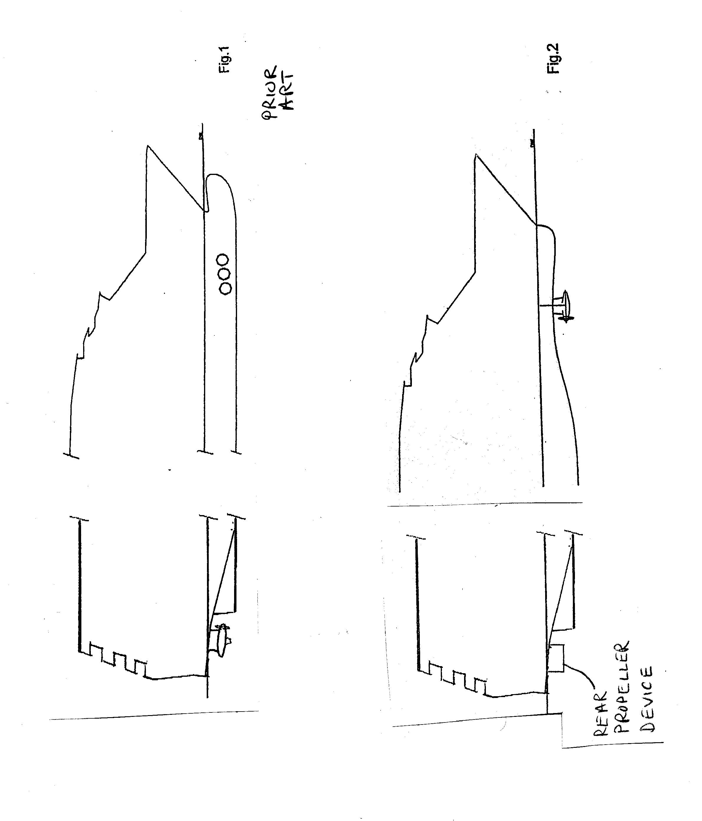
[0023] In a conventional solution according to the case shown in FIG. 1 there are three propeller devices arranged at the front of the ship on both sides, which devices affect only in the lateral direction of the ship, and contribute to the manoeuvering of the ship to quay and to its bringing off the quay respectively, and possibly to performing manoeuvering movements in the harbour area. When a large ship is concerned, the bow-thrusters require a lot of power, which is of no use in the ship's normal steering ahead.

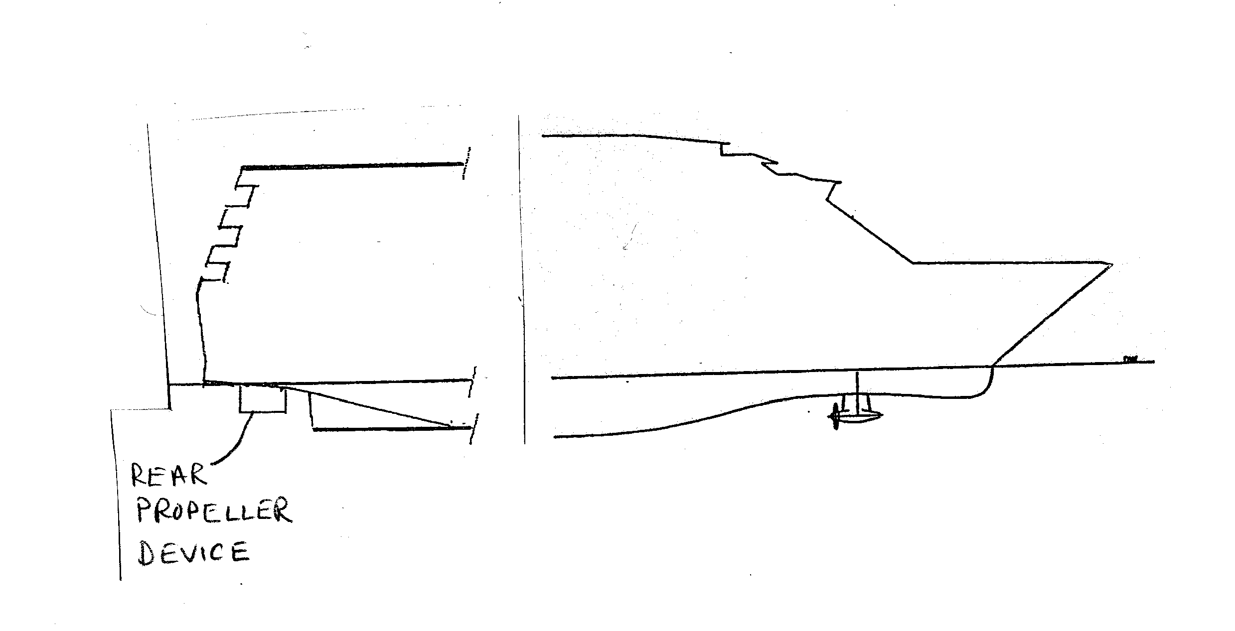
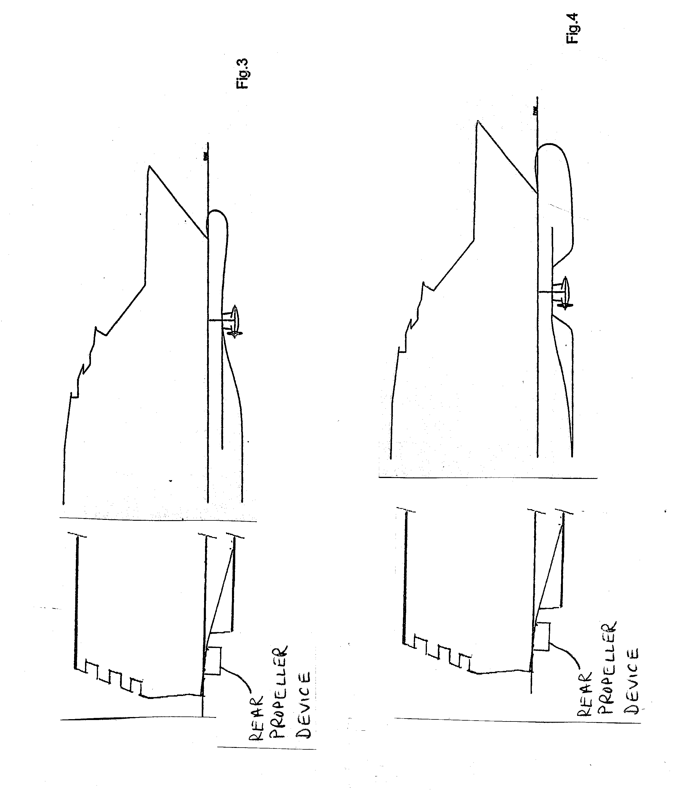
[0024]FIGS. 2-4 show how rudder propeller devices are arranged at the forebody of a vessel. Free turning of the rudder propeller device requires space and therefore the underwater hull requires modifications in comparison with traditional solutions. FIG. 2 shows the use of a rudder propeller in a ship lacking a bulb. In FIG. 3 there is a small low bulb and in FIG. 4 a large deep bulb.

[0025]FIGS. 5-8 show how one or several rudder propeller devices can be arranged at the...


PUM


Abstract

A large ship having a hull about 100 meters or more in length, so that the ship is suited for transoceanic traffic, with a narrow wedge-like bow and the broadest part of the underwater hull being located amidships, includes at least one steerable rudder propeller device at the forebody of the ship. The steerable rudder propeller device(s) at the forebody of the ship substantially provide(s) the steering and control of the ship and produce(s) a part of the propulsive force pushing the ship forward at least substantially within all speed ranges. In harbour manoeuvering, the steerable rudder propeller device(s) at the forebody of the ship provide(s), as needed, at least about 20% of the ship's total propulsive power. When steering ahead in sea traffic, the steerable rudder propeller device(s) at the forebody of the ship provide(s) at most about 10% of the ship's total propulsive power.

Description

[0001] This is divisional of U.S. patent application Ser. No. 10 / 543,582 filed Aug. 11, 2005, which is a national stage application filed under 35 USC 371 based on International Application No. PCT / FI2004 / 000024 filed Jan. 19, 2004, and claims priority under 35 USC 119 of Finnish Patent Application No. 20030132 filed Jan. 30, 2003.BACKGROUND OF THE INVENTION [0002] The present invention relates to a steering and propulsion arrangement in a large ship suited for transoceanic traffic, which arrangement comprises a number of propulsion devices situated partly at the rear and partly at the forebody of the ship. [0003] From prior art are known steerable rudder propeller devices, which are driven either by a mechanical force transmission means or an electric motor arranged inside the device. The device enables the turning of the propeller device about its vertical axis, and the propulsive force of the propeller can thus be turned in desired direction. In addition, the propeller's rotation...

Claims


Application Information

Patent Timeline
IPC IPC(8): B63B1/00B63B1/06B63H5/08B63H5/125
CPCB63B1/06B63H5/08B63H2005/1254B63H2005/005B63H5/125B63H25/42
Inventor SIRVIO, JARISALMELA, OLLIANDERSSON, JANNELEVANDER, KAI
Owner AKER FINNYARDS OY PL 132
Why Eureka
Try Eureka