Integrated Wiring Member for Solar Cell Module, Solar Cell Module Using the Same, and Manufacturing Methods Thereof

a solar cell module and solar cell technology, applied in the direction of manufacturing tools, pv power plants, coatings, etc., can solve the problems of solder-plated wiring materials, insulation failure, and variation in outer appearance, so as to suppress insulation performance failure, reduce external variation, and improve aesthetics

Active Publication Date: 2008-03-06
SHARP KK
View PDF3 Cites 59 Cited by
  • Summary
  • Abstract
  • Description
  • Claims
  • Application Information

AI Technical Summary

Benefits of technology

[0064] According to the present invention, it is possible to realize a solar cell module with reduced external variation and improved aesthetic sense. Further, it is possible to suppress insulation performance failure due to a variation in distance to a module end, and to improve an insulation property of a solar cell module.
[0065] In addition, a portion, other than a connection portion, of a wiring member or at least a part of the portion is coated with an insulative coating member, so that improved insulation performance and improved aesthetic sense can be achieved. Moreover, this coating member is allowed to have a color identical to those of peripheral members. As a result, the coating member is assimilated into the surface of the solar cell module; thus, an aesthetic sense can be further improved.
[0066] In addition, as an end-face sealing member for the solar cell module, there is used silicone resin, EVA resin, an elastomer or the like which enters a liquid state once upon manufacturing of the solar cell module. Therefore, even when generation of air bubbles or separation occurs, a wiring member is coated with an insulative coating member, so that insulation performance between the wiring member and peripheral members can be ensured sufficiently.
[0067] The solar cell module according to the present invention is formed into such a shape that a wiring member connecting between adjoining solar cells is connectable, so that work for connection by soldering in a wiring step in a solar cell module production process can be facilitated and a time for the work can be significantly reduced.
[0068] In the manufacturing method of a solar cell module according to the present invention, a wiring member is formed in accordance with a shape of a connection part, the wiring member is arranged in the connection part, and a connection terminal of a solar cell is connected by soldering to a connection portion of the wiring member. More specifically, formed wiring members are integrated with each other, so that work for connection by soldering in a wiring step in a solar cell module production process can be facilitated and a time for the work can be significantly reduced.
[0069] Since bare portions are aligned orderly, automated work for connection by soldering can be readily performed as compared with the conventional technique and cost reduction can be achieved. Thus, an inexpensive solar cell module can be provided.

Problems solved by technology

Therefore, when the EVA resin is filled into a mold for a solar cell module and, then, is solidified and molded by application of heat at about 150° C., there arises the following problem.
That is, air bubbles are generated in the EVA resin and the EVA resin is partly separated from a wiring member and the like, resulting in insulation failure.
Herein, there arises a problem that a solder-plated wiring material having a silver-color surface is externally conspicuous on a solar cell module formed by a solar cell which is entirely dark in color.
Consequently, it is difficult to perform positional adjustment and to control arrangement of wiring members when the EVA resin filled into a mold is thermally solidified, so that a variation in outer appearance is occurred.
However, a coating member which has a color identical to that of back cover 17 and ensures a heat-resistant property is rare and expensive.
Consequently, such a coating member is not practically used.
That is, coating member 441, which is insufficient in heat-resistant property when connecting pieces 12c are connected by soldering to bare portions 42a1 and 42a2, is broken due to heat generated in the connection by soldering, resulting in insulation failure.
That is, it is necessary that a wiring member obtained by integrating wiring members 42 and 44 with each other is arranged so as to weave the front and back sides of adjoining cell units alternately, resulting in complicated work.
. . ), the wiring member must be arranged so as to weave the front and back sides of adjoining cell units alternately, resulting in complicated work.

Method used


Image

  • Integrated Wiring Member for Solar Cell Module, Solar Cell Module Using the Same, and Manufacturing Methods Thereof
  • Integrated Wiring Member for Solar Cell Module, Solar Cell Module Using the Same, and Manufacturing Methods Thereof
  • Integrated Wiring Member for Solar Cell Module, Solar Cell Module Using the Same, and Manufacturing Methods Thereof

Examples


embodiment 1

(Solar Cell Module)

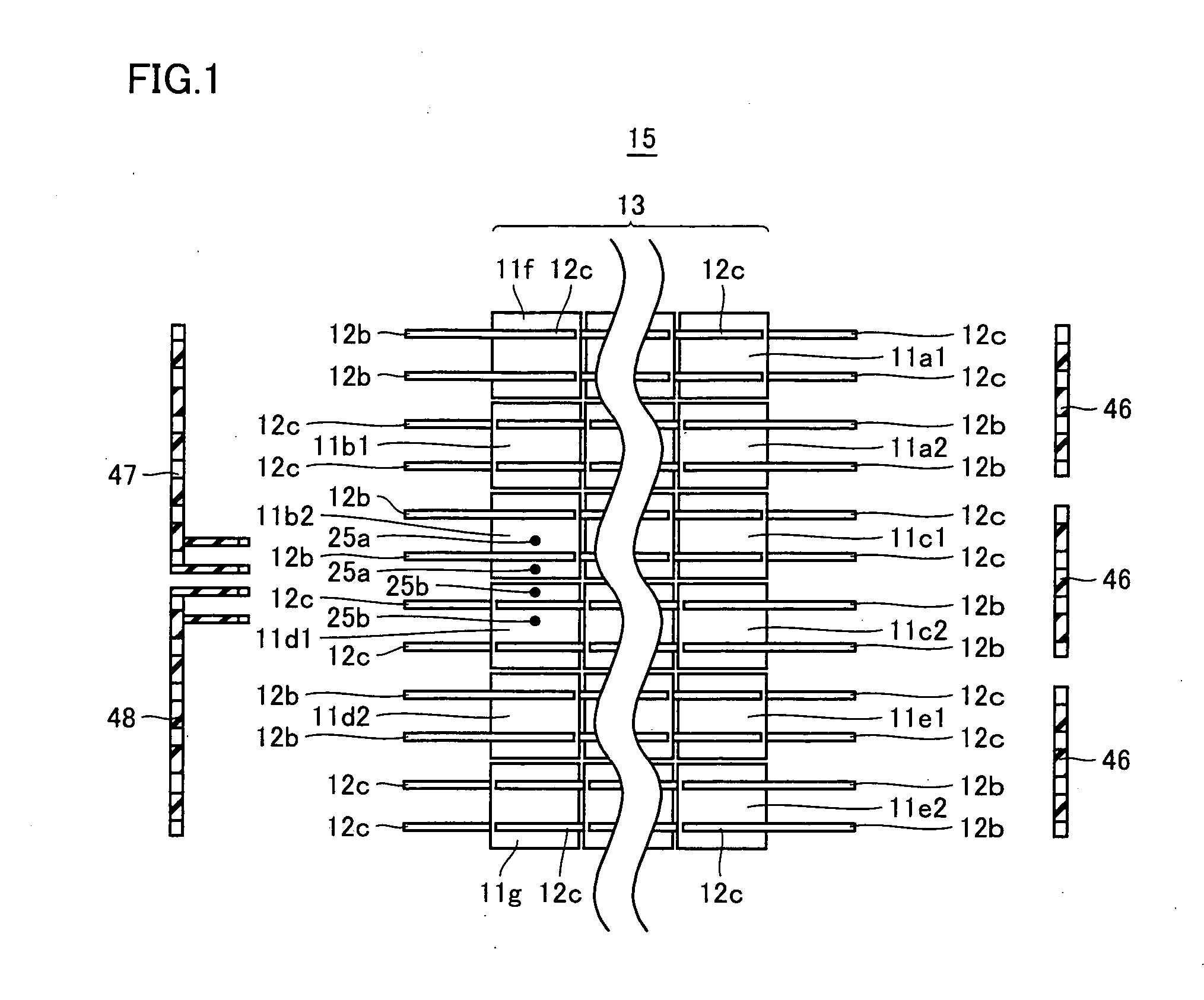
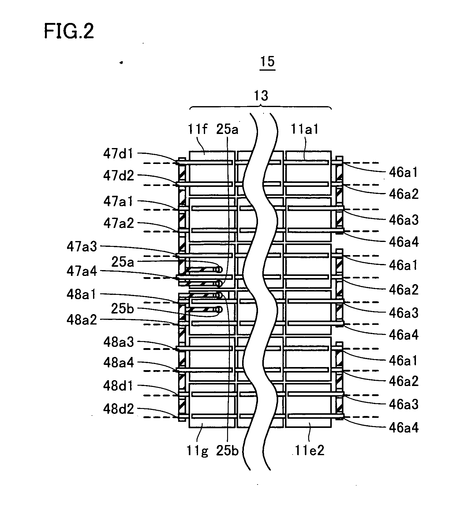
[0137] With reference to FIG. 1, a solar cell module according to the present invention has the following structure. That is, a plurality of solar cells 11 are arranged in line and are electrically connected to each other to thereby form a cell unit 13. Then, a plurality of cell units 13 formed as described above are arranged side by side, and the adjoining solar cells (e.g., 11a1 and 11a2, 11b1 and 11b2, and the like) located at respective both ends of cell units 13 are electrically connected to each other through integrated wiring members 46, 47 and 48; thus, the solar cells arranged in a form of a matrix 15 are entirely connected to each other in series. In the present invention, each of wiring members 46, 47 and 48 for electrically connecting between the solar cells is of an integrated type, unlike a conventional wiring member.

[0138] In an integrated wiring member according to the present invention, a portion other than a connection portion, in which solar ...

embodiment 2

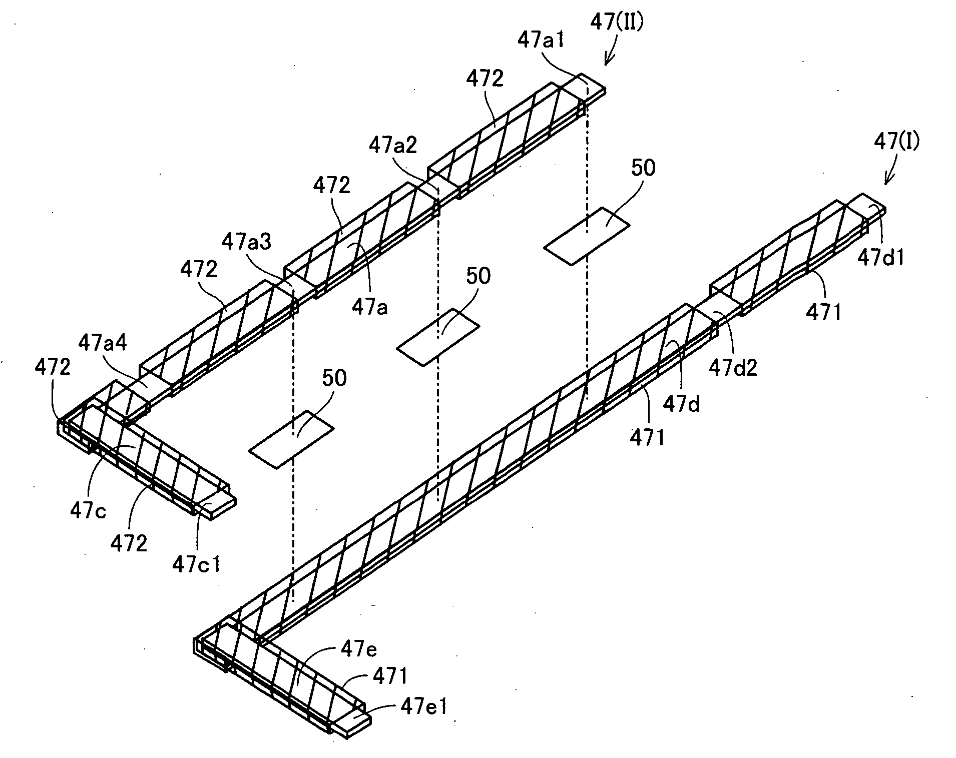
[0211] In Embodiment 2, description will be given of another embodiment of the integrated wiring member according to the present invention. FIG. 10 is a perspective view illustrating first wiring member 47(I) and second wiring member 47(II) separated from each other in first integrated wiring member 47. FIG. 11 is a perspective view illustrating first integrated wiring member 47 in which first wiring member 47(I) and second wiring member 47(II) separated from each other in FIG. 10 are integrated with each other. FIG. 12 is a perspective view illustrating first wiring member 48(I) and second wiring member 48(II) separated from each other in second integrated wiring member 48. FIG. 13 is a perspective view illustrating second integrated wiring member 48 in which first wiring member 48(I) and second wiring member 48(II) separated from each other in FIG. 12 are integrated with each other.

[0212] As illustrated in FIGS. 10 and 12, Embodiment 2 is similar to Embodiment 1 except that there...

embodiment 3

[0218] In Embodiment 3, description will be given of still another embodiment of the integrated wiring member according to the present invention. FIG. 15 is a perspective view illustrating first wiring member 47(I) and second wiring member 47(II) separated from each other in first integrated wiring member 47. In FIG. 15, second wiring member 47(II) is coated with no coating member. FIG. 16 is a perspective view illustrating first integrated wiring member 47 in which first wiring member 47(I) and second wiring member 47(II) separated from each other in FIG. 15 are integrated with each other. FIG. 17 is a perspective view illustrating a state where the first integrated wiring member in FIG. 16 is coated with the coating member.

[0219]FIG. 18 is a perspective view illustrating first wiring member 48(I) and second wiring member 48(II) separated from each other in second integrated wiring member 48. In FIG. 18, second wiring member 48(II) is coated with no coating member. FIG. 19 is a pe...


PUM


Abstract

The present invention provides an integrated wiring member (46, 47, 48) for a solar cell module, including a first wiring member, a second wiring member, and an insulating and protecting film for insulating the first wiring member and the second wiring member from each other. Herein, the first wiring member and the second wiring member are integrated with each other through the insulating and protecting film.

Description

TECHNICAL FIELD [0001] The present invention relates to an integrated wiring member for a solar cell module, a solar cell module using the same, and manufacturing methods thereof. BACKGROUND ART [0002] A typical solar cell module has the following structure. That is, a plurality of solar cells are arranged in line and are electrically connected to each other to thereby form a cell unit. Then, a plurality of cell units formed as described above are arranged side by side, and the adjoining solar cells located at respective both ends of the cell units are electrically connected to each other through solder-plated wiring members; thus, the solar cells arranged in a form of a matrix are entirely connected to each other in series. Herein, the solar cells and the wiring members are insulated from and protected from the outside by filling resin (EVA (Ethylene Vinyl Acetate) resin), an end-face sealing member (silicone resin) and the like. In this case, the EVA resin has a thermoplastic prop...

Claims


Application Information

Patent Timeline
Patent Type & Authority Applications(United States)
IPC IPC(8): H01L31/05H01L31/04
CPCY02E10/50H01L31/0504H01L31/0201H01L31/05
Inventor NAKAMURA, MORITAKA
Owner SHARP KK
Why Eureka
Try Eureka