Antenna and portable electronic device

Active Publication Date: 2008-03-06
LENOVO INNOVATIONS LTD HONG KONG
View PDF7 Cites 35 Cited by
  • Summary
  • Abstract
  • Description
  • Claims
  • Application Information

AI Technical Summary

Benefits of technology

[0024] The present invention can ensure reliable communication with a reader/writer for a slight electromagnetic field whose loop antenna has a re

Problems solved by technology

Because the conventional antenna coil used for RFID have a simple structure of having a plurality of turns in a spiral form as shown in FIGS. 14A and 14B, however, it is difficult to make the antenna coil compatible with both of the aforementioned two types of RFID systems.
That is, if the loop diameter of the RFID antenna to be m

Method used


Image

  • Antenna and portable electronic device
  • Antenna and portable electronic device
  • Antenna and portable electronic device

Examples


first embodiment

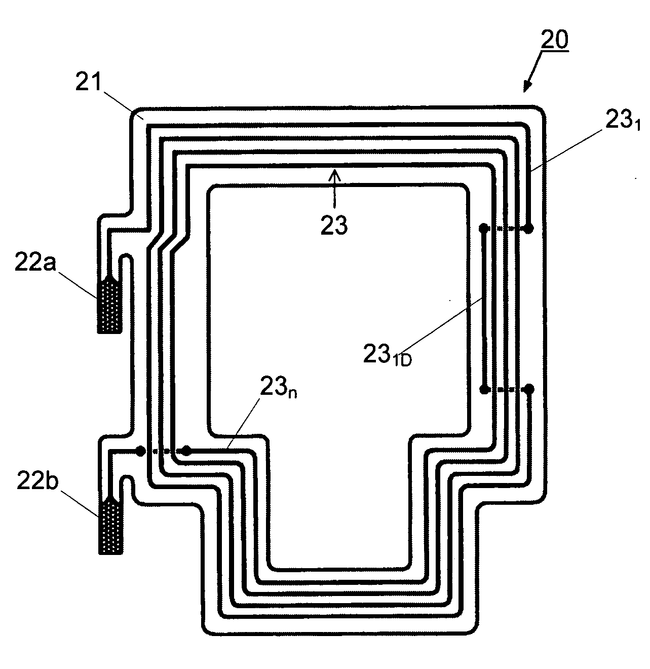
[0081] The RFID antenna 20 according to the first embodiment of the present invention will be explained referring to FIGS. 6A and 6B. FIG. 6A is a plan view showing the configuration of the RFID antenna 20 according to the first embodiment, and FIG. 6B is a perspective view showing a conductive coil 23 of the RFID antenna 20 shown in FIG. 6A.

[0082] The RFID antenna 20 according to the first embodiment includes a base film 21, the antenna terminals 22a, 22b and the conductive coil 23, as shown in FIG. 6A.

[0083] The base film 21 is formed by a flexible board with its shape matching with the shape and size of the battery lid 8. As shown in FIG. 6A, the base film 21 has a center portion open, and a conductive pattern formed in a spiral form on one side thereof, thereby forming a loop antenna. That is, the size of the opening of the base film 21 is based on the size of the loop diameter that is required of the RFID antenna 20.

[0084] The conductive coil 23 is formed by a planar coil wh...

second embodiment

[0096] Although the curved portion 231D that compensates for the magnetic field strength at the center portion of the RFID antenna 20 is formed by bending the outermost coil turn 231 of the conductive coil 23 of the RFID antenna 20 in the first embodiment, a portion other than the outermost coil turn 231 may be bent.

[0097] The RFID antenna 20 and the conductive coil 23 in this case are shown in FIGS. 8A and 8B. As shown in those diagrams, the conductive coil 23 formed at the RFID antenna 20 according to the second embodiment has an antenna pattern provided by bending a part of a second coil turn 232 (e.g., linear portion) which is inward of the outermost coil turn 231 by one turn to form a curved portion 232D which is placed inward of the innermost coil turn 23n.

[0098] While the RFID antenna 20 of the first embodiment which has the outermost coil turn 231 bent can make the magnetic field strength at the center portion of the loop antenna higher than that of the conventional RFID a...

third embodiment

[0105] The first and second embodiments employ the configurations where the magnetic field strength at the center portion of the antenna is compensated for by bending a part of the conductive coil 23. Alternatively, a part of the conductive coil 23 (e.g., linear portion) may be branched to form a conductive pattern which compensates for the magnetic field strength at the center portion of the antenna.

[0106] An example of the configuration of the third embodiment where the outermost coil turn 231 of the conductive coil 23 is branched will be described referring to FIGS. 10A and 10B. FIG. 10A is a plan view showing the RFID antenna 20 according to the third embodiment, and FIG. 10B is a perspective view showing the conductive coil 23 according to this embodiment.

[0107] As shown in FIGS. 10A and 10B, the feature of the conductive coil 23 according to the third embodiment lies in that the conductive coil 23 has an antenna pattern having a bypass portion 231S formed by branching the co...


PUM


Abstract

A portable electronic device having an RFID function has an RFID antenna having a planar coil formed by winding a conductor. The RFID antenna is a loop antenna having a loop diameter corresponding to RFID with a strong electromagnetic field characteristic, and has an antenna pattern where a part of its coil turn which is other than an innermost coil turn is placed inward of the innermost coil turn. The antenna pattern can be provided by bending or branching a part of a coil turn of the conductor which is other than the innermost coil turn in such a way that the part of the coil turn is laced inward of the innermost coil turn, thereby ensuring compensation for the magnetic field strength at the center portion of the antenna and achieving excellent communications without a non-communicatable area even with the RFID having a slight electromagnetic field characteristic.

Description

BACKGROUND OF THE INVENTION [0001] 1. Field of the Invention [0002] The present invention relates to an antenna for RFID (Radio Frequency Identification), which communicates with an external device by means of an electromagnetic field signal, and a portable electronic device having the antenna mounted therein. [0003] 2. Description of the Related Art [0004] An electronic money function is realized by installing an RFID function into a portable electronic device such as a cellular phone. In this case, settlement is made through non-contact communication between a portable electronic device with, for example, a reader / writer sited in a shop or the like, or a reader / writer installed in an automatic ticket checking machine or the like for railroads. [0005] In a portable electronic device installed with the RFID function that communicates with an external device by means of an electromagnetic field signal, an antenna coil for RFID is typically provided at a battery retaining section or t...

Claims


Application Information

Patent Timeline
IPC IPC(8): H04Q5/22H01Q11/12
CPCH01Q1/22H01Q1/2208H04M1/0214H01Q7/00H01Q9/27H01Q1/38H01Q7/04
Inventor SHIMIZU, TAKAYUKI
Owner LENOVO INNOVATIONS LTD HONG KONG
Why Eureka
Try Eureka