Eureka AIR delivers breakthrough ideas for toughest innovation challenges, trusted by R&D personnel around the world.

Projection type image display apparatus

a technology of projection type and display apparatus, which is applied in the direction of projectors, optics, instruments, etc., can solve the problems of cumbersome maintenance work and less efficient maintenance work, and achieve the effect of reducing risk, efficient and low-cost maintenance of polarization plates

Inactive Publication Date: 2008-03-06
SANYO ELECTRIC CO LTD
View PDF3 Cites 1 Cited by
  • Summary
  • Abstract
  • Description
  • Claims
  • Application Information

AI Technical Summary

Benefits of technology

[0006]In view of these problems mentioned above, it is an object of the present invention to provide a projection type image display apparatus whose components are arranged in such a way that they can be easily and efficiently replaced even when the display apparatus is installed upside down on a ceiling for example.
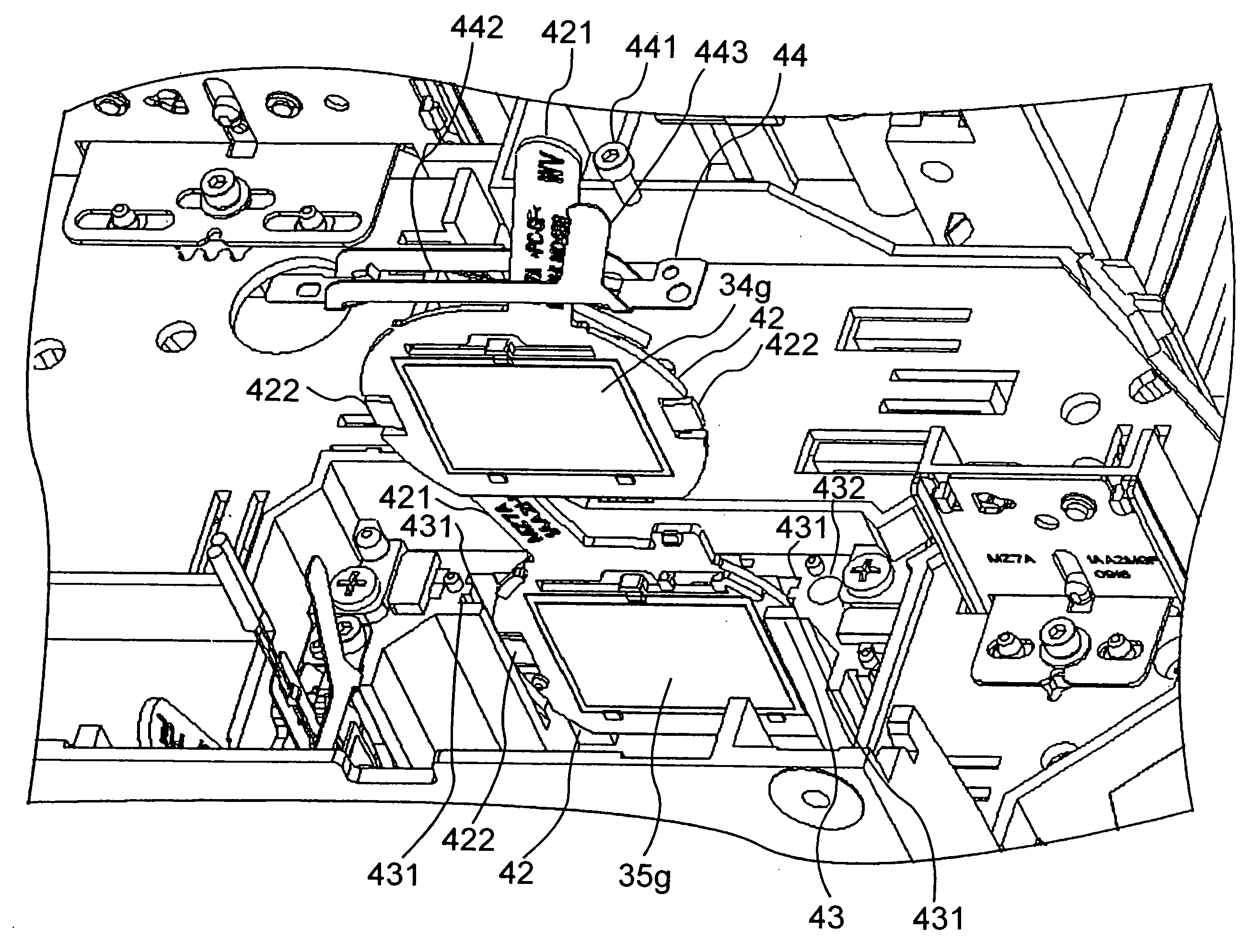
[0014]In this arrangement, if the fixing screws are removed to dismount the prism assembly from the display apparatus installed upside down on a ceiling, the prism assembly does not drop downward, since the prism assembly is then temporarily held in position by the elastic engagement members exerting forces on the prism assembly that exceed the weight of the prism assembly. Thus, parts of the projection type image display apparatus can be replaced quite easily with the projector installed upside down, thereby greatly improving the maintenance efficiency.
[0017]As a result, each screw remains in the through-hole if it is unscrewed by a screw driver and removed from the female thread of the mount section. Thus, one may conveniently work with the next screw without spending time to remove the screw from the screw driver. This adds further efficiency to the maintenance efficiency.
[0023]the first adjusting member is preferably provided, on opposite portions of the periphery thereof, with elastic engagement members made of a resilient resin and adapted to elastically abut against the first groove so as to prevent the first adjusting member from falling downward from the first groove due to its weight if the screws are removed from the second mount section to release the adjusting member stopper even while the projection type image display apparatus is suspended upside down and the lid is opened.
[0028]the second adjusting members are preferably provided on opposite portions of the periphery thereof with elastic engagement members made of a resilient resin and adapted to elastically abut against the second groove so as to prevent the second adjusting member from falling downward from the second groove due to its weight if the screws are removed from the second mount section to release the adjusting member stopper even while the projection type image display apparatus is suspended upside down and the lid is opened.
[0029]Thus, the invention eliminates the risk of the adjusting members falling down during the maintenance together with the polarization plates and optical compensation plates mounted from a projection type image display apparatus suspended upside down from a ceiling even if fixing screws are removed from the adjusting member stopper, thereby enabling efficient and low-cost maintenance of the polarization plates.

Problems solved by technology

If such projection type image display apparatus is installed upside down on the ceiling for example, the prism assembly and optical parts must be supported by hand to prevent them from falling when the screws are removed for replacement, which causes the maintenance work less efficient.
Moreover, replacement of parts of the display apparatus suspended upside down is extremely difficult to do, so that, normally, the display apparatus is dismounted once from the ceiling before the replacement, which makes the maintenance work cumbersome.

Method used


Image

  • Projection type image display apparatus
  • Projection type image display apparatus
  • Projection type image display apparatus

Examples


Embodiment Construction

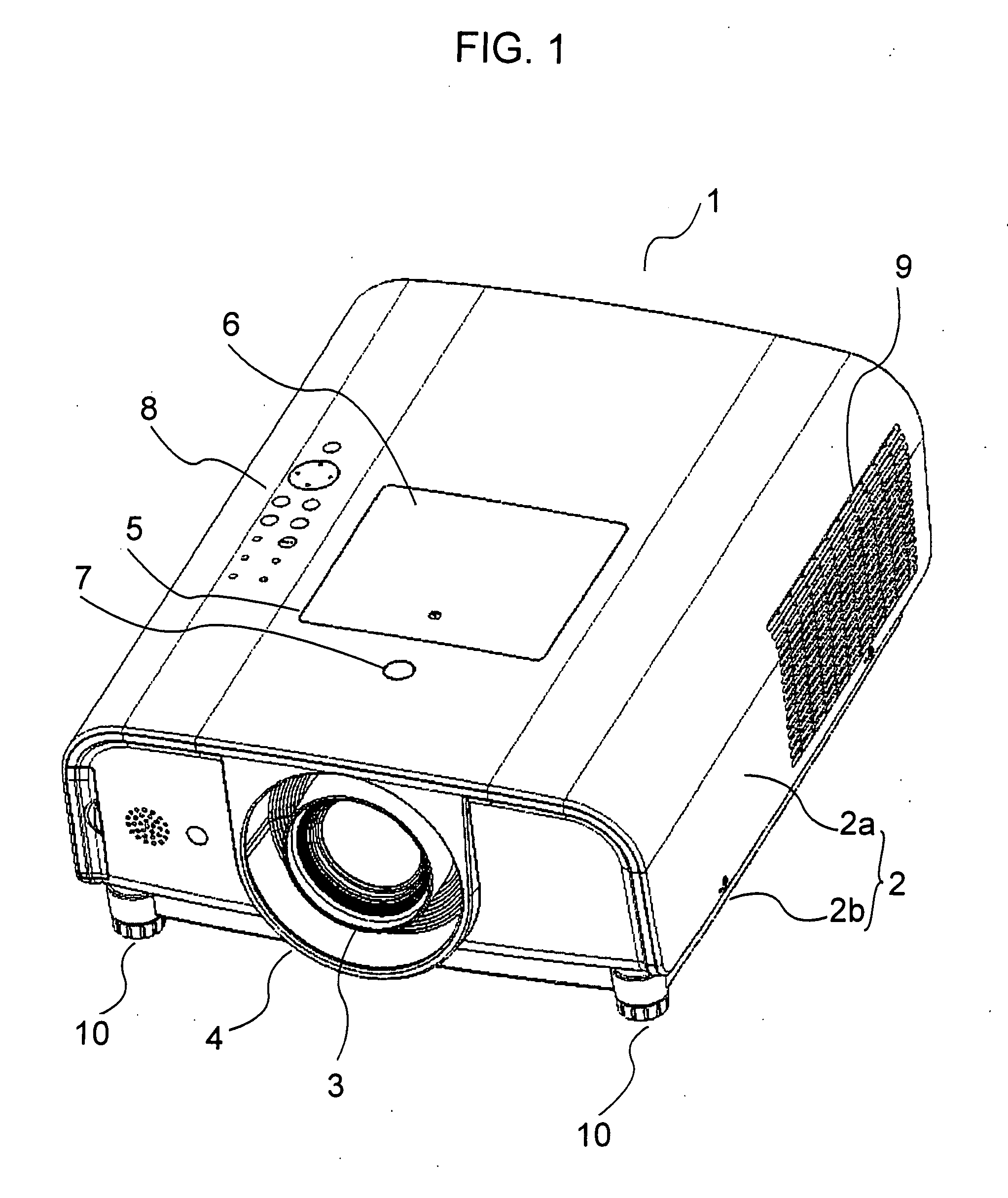
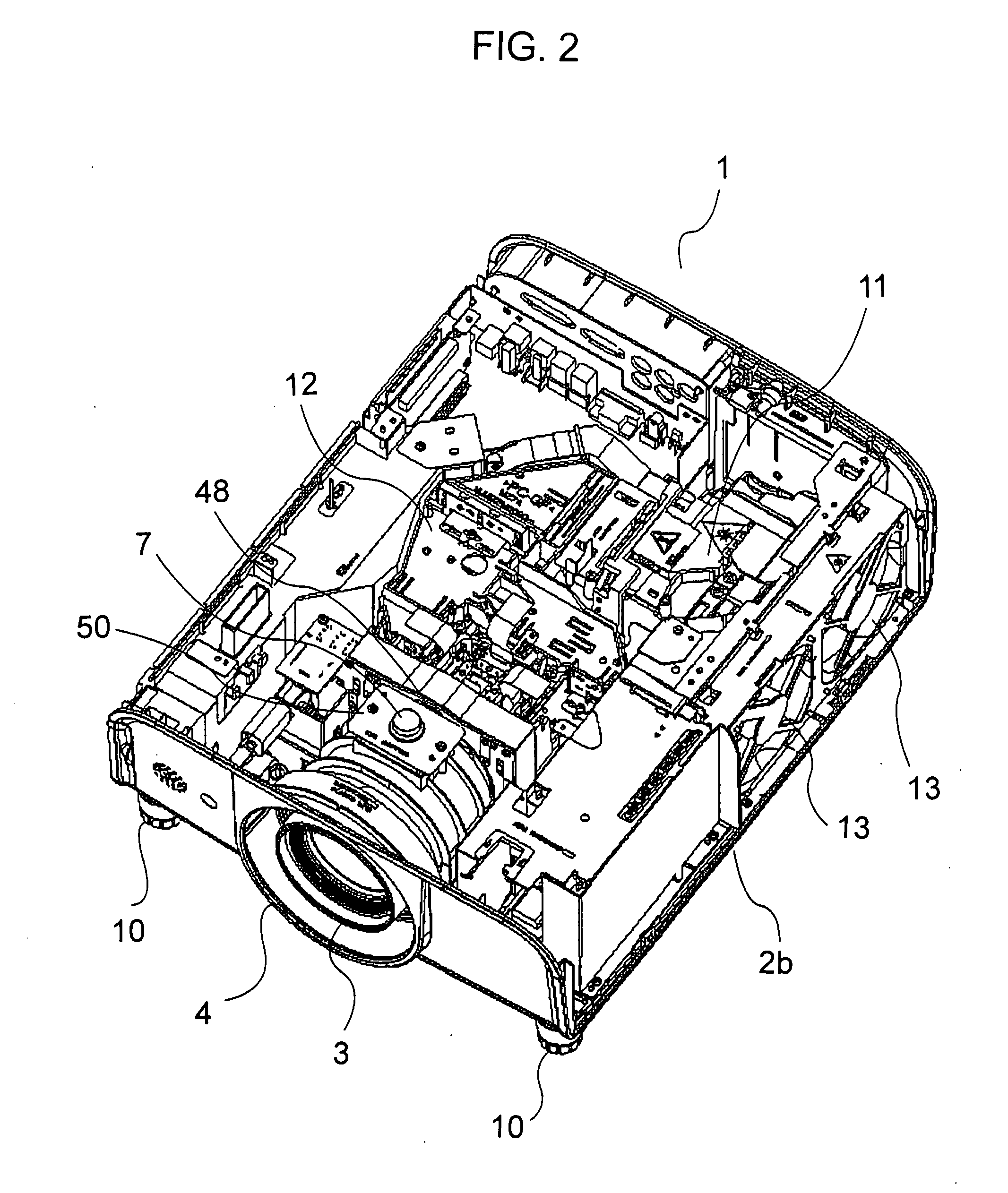
[0051]The invention will now be described in detail by way of example with reference to the accompanying drawings. Referring to FIG. 1, there is shown in oblique perspective view a projection type image display apparatus in the form of a liquid crystal projector in accordance with one embodiment of the invention. FIG. 2 is an oblique perspective view of the projector with its upper case removed.

[0052]As seen in FIG. 1, this liquid crystal projector 1 has a casing 2, which consists of an upper casing 2a and a lower casing 2b. The internal structure of the projector will appear when the upper casing 2a is removed, as shown in FIG. 2.

[0053]There is provided at the center of the front end of the casing 2 a projection window 4 where a projection lens 3 is exposed. Formed in the central area of the upper end of the casing 2 is a maintenance opening 5 and a lid 6 for closing the opening 5 as needed. There are also provided in front of the maintenance opening 5 a projection lens removal but...


PUM


Abstract

An openable lid is provided to cover an opening formed in the upper end of a casing of a projection type image display apparatus. Formed on the base of the casing and underneath the opening is a first mount section, on which a plinth is mounted with fixing screws. A prism assembly incorporating at least three liquid crystal panels and three polarization plates for RGB colors integrally attached to a color compounding prism is securely fixed on the plinth. The first mount section is provided with engagement members fixed thereon for temporarily holding the plinth that bears thereon the prism assembly to thereby prevent the plinth from falling downward if the screws are removed to dismount the plinth from the first mount section even when the image display apparatus is installed upside down on a ceiling for example and the lid is open. This permits easy replacement of parts of the projection type image display apparatus that is installed upside down, and thus greatly improves maintenance efficiency of the projector.

Description

FIELD OF THE INVENTION[0001]This invention relates to a projection type image display apparatus, and more particularly, to a maintenance technology for conveniently carrying out maintenance of such display apparatus.BACKGROUND OF THE INVENTION[0002]Due to degradation after a certain period of use, part or all of the liquid crystal panels, polarization plates, and optical compensation plates for RGB components assembled for use in a projection type image display apparatus such as a liquid crystal projector need to be occasionally replaced. Normally, in order to replace these parts in the maintenance, it is necessary to open the projector's casing, which adds extra manual steps to the maintenance.[0003]To solve such a problem as mentioned above, Japanese Patent Application Laid Open No. H11-46077 discloses a technique that enables replacement and adjustment of parts without opening the casing itself, in which the casing is provided with an opening for maintenance formed in the upper e...

Claims


Application Information

Patent Timeline
IPC IPC(8): G03B21/14
CPCG03B21/14G03B21/145
Inventor HIROUCHI, YASUYUKIYOSHIMURA, TAICHI
Owner SANYO ELECTRIC CO LTD
Why Eureka
Eureka Blog
Learn More