Image transmission apparatus

a transmission apparatus and image technology, applied in the field of image transmission apparatus, can solve the problems of image data being transmitted to the wrong destination, inconvenient and even extremely tedious for users, and many destinations that are inconvenient and even extremely tedious for users, and achieve the effect of high level of convenien

Active Publication Date: 2008-03-06
KONICA MINOLTA BUSINESS TECH INC
View PDF5 Cites 19 Cited by
  • Summary
  • Abstract
  • Description
  • Claims
  • Application Information

AI Technical Summary

Benefits of technology

[0015]Furthermore, an image transmission program according to one aspect of the present invention is an image transmission program embodied in a computer readable medium and being executed by an image transmission apparatus that transmits image data to an image processing apparatus that processes the image data in accordance with a destination name of the image data, the image transmission apparatus storing (a) a shared list that is shared by a plurality of users and that corresponds destination names with image processing apparatuses, and (b) a plurality of individual lists, each of which is administered by a different one of the plurality of users and that corresponds the destination names with apparatuses other than the image processing apparatuses corresponded therewith in the shared list, the image transmission program causing the image transmission apparatus to perform the steps of: receiving a destination name that is a name of a destination of image data; transmitting the image data in accordance with an instruction from a user; and judging whether or not the transmission of the image data succeeds or fails, wherein, when it is judged that transmission of the image data to the image processing apparatus corresponded with the destination name in the shared list has failed, the image data is transmitted to an apparatus that is corresponded with the destination name in the individual list administered by the user who instructed the transmission. This reduces the effort for the user to designate a destination when transmitting an image, thus achieving a high level of convenience. In particular, an individual list that is referred to when the image data cannot be transmitted to the image processin

Problems solved by technology

A further problem is that transmission of image data may fail for reasons such as the state of the MFP on the reception side.
When there is a relatively large number of destinations to which image data is to be transmitted, it is not just having to store each of the numerous destinations that is inconvenient and even extremely tedious for the user, but also having to input such desti

Method used


Image

  • Image transmission apparatus
  • Image transmission apparatus
  • Image transmission apparatus

Examples


first embodiment

1. First Embodiment

[0043]The image communication system relating to the first embodiment of the present invention includes a plurality of MFPs. A feature of the image communication system is that each MFP includes a destination user list set individually for the MFP by an administrator, and a plurality of address books, each of which is set by a different individual user of the MFP, and when image data is to be transmitted, the destination is automatically set based on the user list and the address book of the user sending the image data.

(1) Structure of the Image Communication System

[0044]First, a description is given of the structure of the image communication system relating to the present embodiment.

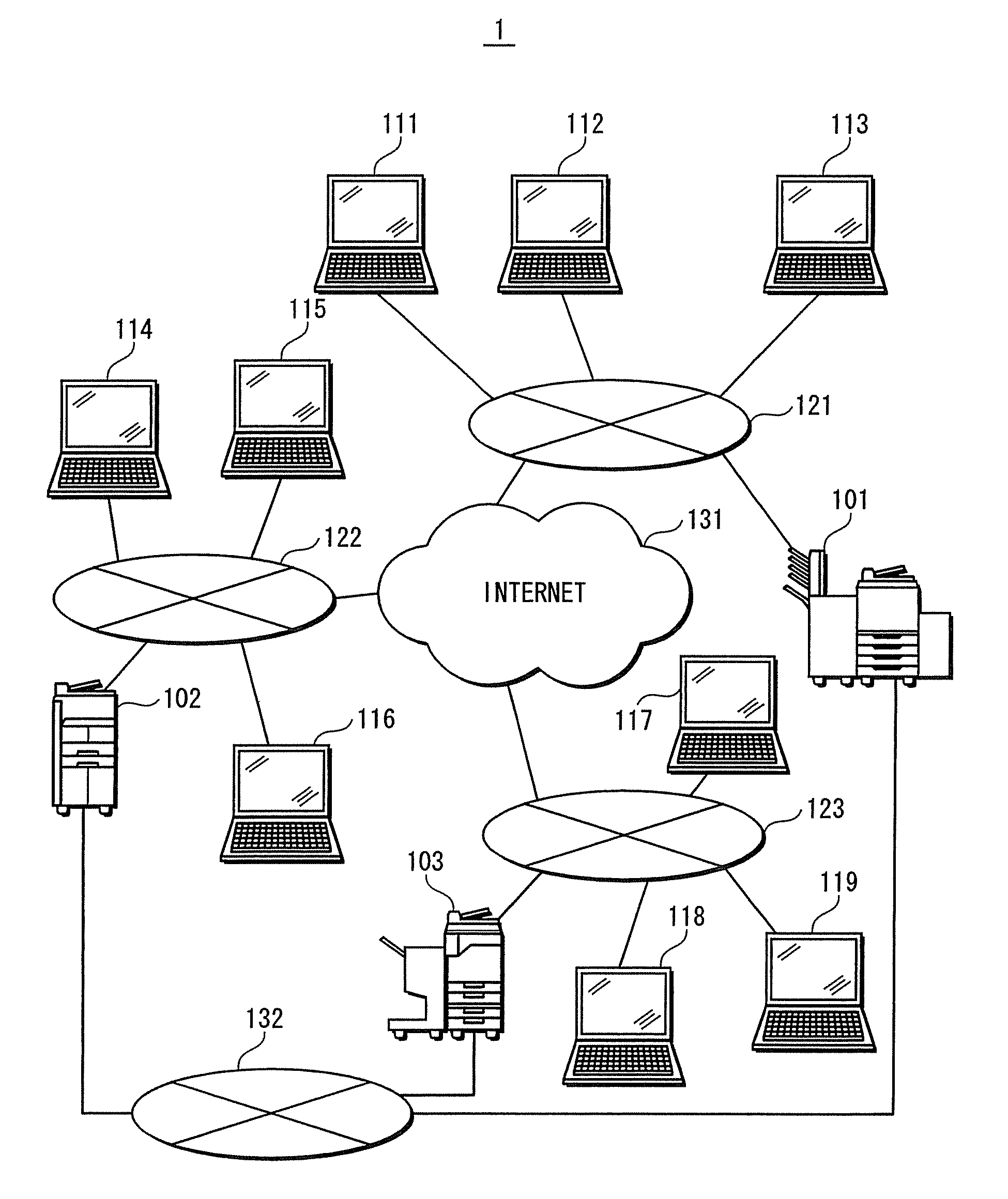
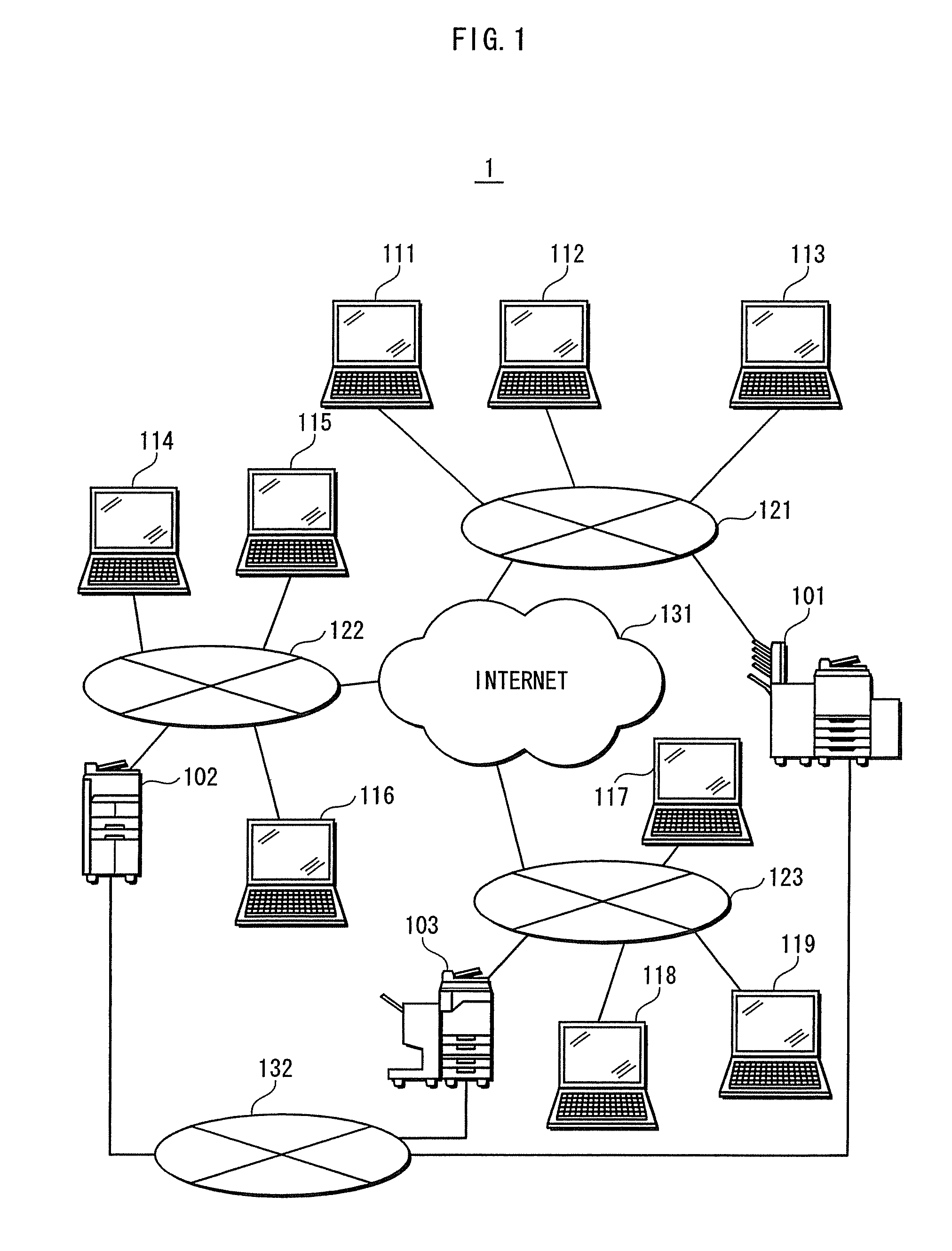
[0045]As shown in FIG. 1, an image communication system 1 is composed of MFPs 101 to 103, personal computers (hereinafter called “PC(s)”) 111 to 119, local area networks (hereinafter called “LAN(s)”) 121 to 123, the Internet 131, and a circuit switching network 132.

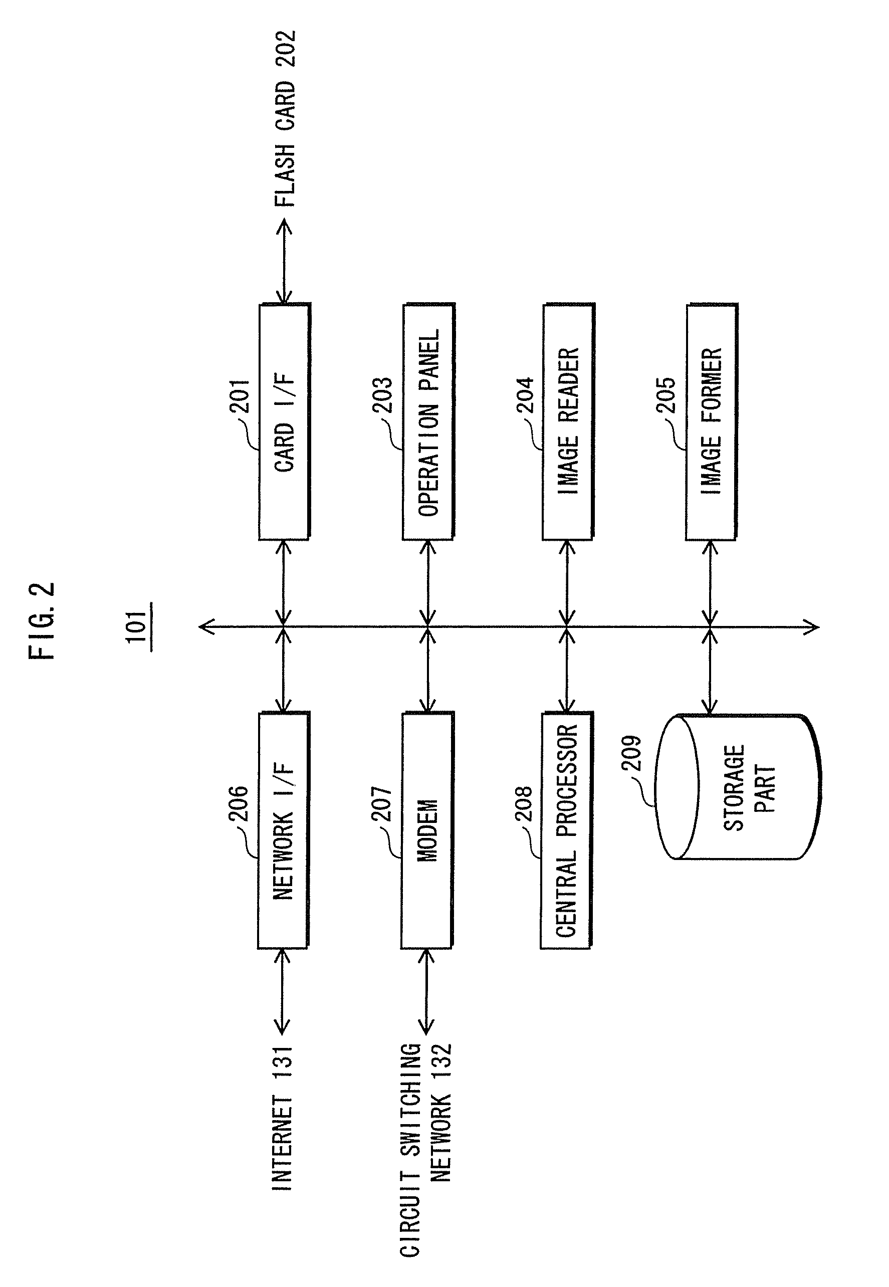
[0046]The MFP 101 ...

second embodiment

2. Second Embodiment

[0099]Next a description is given of an image communication system relating to a second embodiment of the present invention. While the image communication system of the second embodiment has basically the same structure as the image communication system of the first embodiment, it differs in that the transmission-side MFP records transmission history of image data.

[0100]The following description focuses principally on the aspects that differ from the first embodiment.

(1) Communication Sequence

[0101]First a description is given of the communication sequence in the image communication system of the present embodiment. Note that in the same way as the first embodiment, the following description is of an example of the transmission-side MFP being the MFP 103, the reception-side MFP being the MFP 101, and the destination user being person A (PC 111).

[0102]As shown in FIG. 11, upon receiving a transmission instruction to transmit image data to person A, the MFP 103 tra...

third embodiment

3. Third Embodiment

[0115]Next a description is given of an image communication system relating to the third embodiment. While the image transmission system of the present embodiment has basically the same structure as the image transmission system of the first embodiment, it differs in that it receives, as the destination of the image data, a designation of a group that includes a plurality of destinations. The following description focuses principally on the aspects that differ from the first embodiment.

[0116]The communication sequence in the image communication system of the present embodiment is the same as the communication sequence in the image communication system of the first embodiment, and therefore a description thereof is omitted. A description of the operations of the reception-side MFP is omitted for the same reason, and the following describes only the operations of the transmission-side MFP.

[0117]As shown in FIG. 14, upon receiving a read instruction to read image dat...


PUM


Abstract

A transmission-side MFP receives a user name, checks whether the user name is registered in a destination user list, and if so, transmits image data to a reception-side MFP. If an ACK is received, the transmission-side MFP displays that transmission was successful. When a NACK is received or a time out occurs, the transmission-side MFP checks whether the user name is registered in an individual address book, and if so, transmits the image data using a corresponding transmission method. If an ACK is received, the transmission-side MFP displays that transmission was successful. If a timeout occurs, the transmission-side MFP displays that transmission failed.

Description

CROSS-REFERENCE TO RELATED APPLICATIONS[0001]This application is based on application No. 2006-235525 filed in Japan, the content of which is hereby incorporated by reference.BACKGROUND OF THE INVENTION[0002](1) Field of the Invention[0003]The present invention relates to an image transmission apparatus, and in particular to a technique for improving convenience for the user when transmitting image data.[0004](2) Description of the Related Art[0005]With significant progress in information communication techniques in recent years, it is now possible to select from among various communication methods such as e-mail, FTP (File Transfer Protocol) and SMB (Server Message Block), in addition to facsimile. Accordingly, MFPs (Multi Function Peripherals) are equipped with functions that enable various methods to be used for transmitting and receiving image data obtained by reading a document with a scanner.[0006]It is the sender who determines which of the communication functions included in...

Claims


Application Information

Patent Timeline
IPC IPC(8): H04N1/00
CPCH04N1/00212H04N1/00347H04N1/32037H04N1/32048H04N2201/3276H04N2201/0094H04N2201/3205H04N2201/3208H04N2201/3209H04N1/32106
Inventor UCHIDA, HISASHIINUI, KAZUOTSUBOI, TOMOHINO, HIDEKIITOH, AYUMI
Owner KONICA MINOLTA BUSINESS TECH INC
Why Eureka
Try Eureka