Perpendicularly feeding type magnetic head having adjustable input impedance, manufacturing method thereof, head suspension assembly, and magnetic storage device

Inactive Publication Date: 2008-03-06
FUJITSU LTD
View PDF21 Cites 16 Cited by
  • Summary
  • Abstract
  • Description
  • Claims
  • Application Information

AI Technical Summary

Benefits of technology

[0009]On the other hand, a read head element, particularly, of the TMR head and GMR head is improved through reduction in thickness and the dielectric strength thereof, for the applied volta

Problems solved by technology

When the dielectric strength of the read head element is lowered, adverse effects and breakdown of the element by electrostatic discharge (ESD) becomes a significant problem.
However, in the thin film magnetic heads having a read head element to which a sense current is applied in the direction perpendicular to the film surface like the TMR head and GMR head of the CPP structure, it is impossible to shield the read head element by grou

Method used


Image

  • Perpendicularly feeding type magnetic head having adjustable input impedance, manufacturing method thereof, head suspension assembly, and magnetic storage device
  • Perpendicularly feeding type magnetic head having adjustable input impedance, manufacturing method thereof, head suspension assembly, and magnetic storage device
  • Perpendicularly feeding type magnetic head having adjustable input impedance, manufacturing method thereof, head suspension assembly, and magnetic storage device

Examples


Example

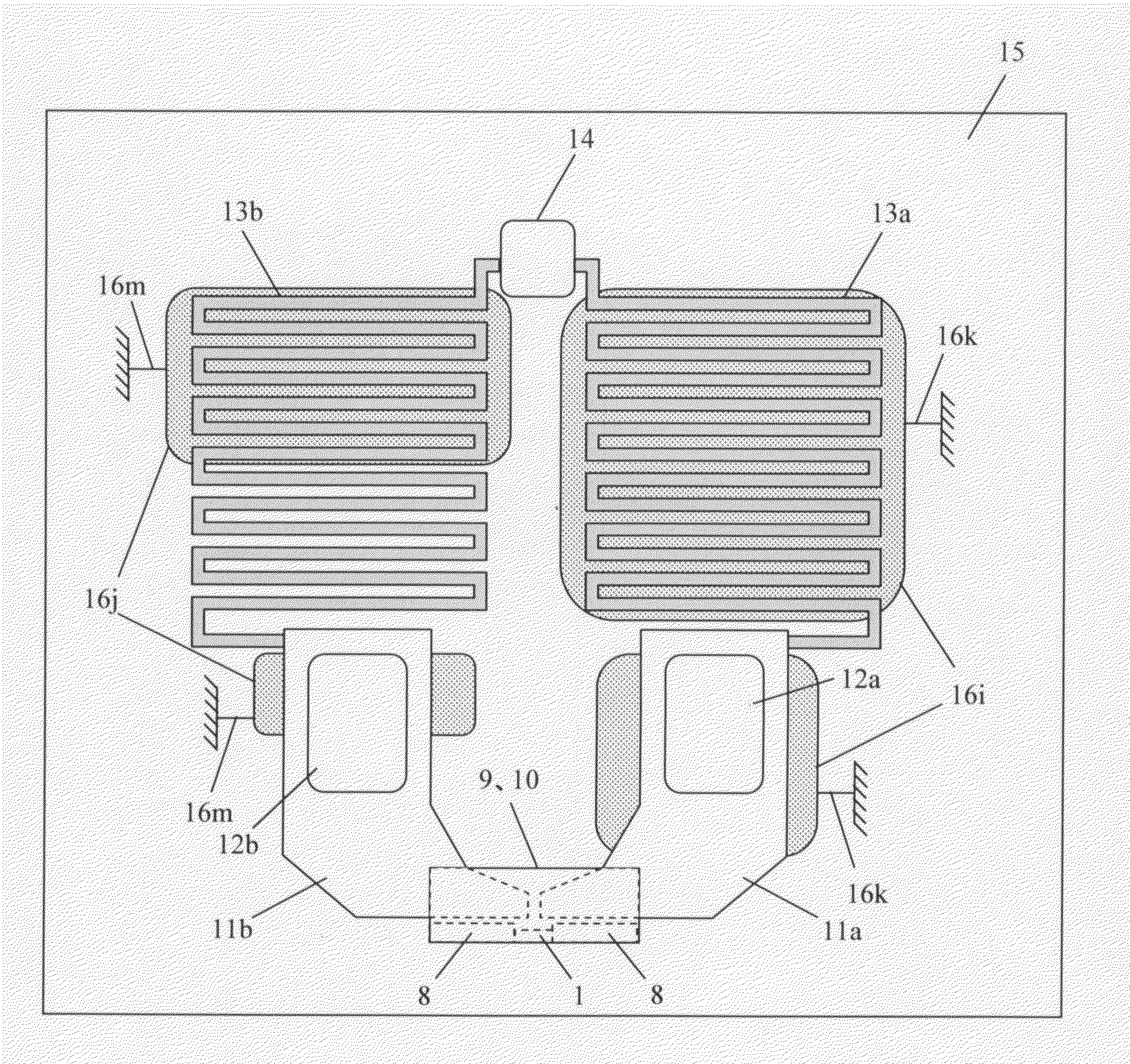
[0041]FIG. 6 is a plan view of a third embodiment of the magnetic head of the present invention viewed in the direction perpendicular to a film surface thereof. In this embodiment, electrically shielded layers 16i, 16j are placed between a pair of the first conductive wires (lead-out wires 11a, 11b, bonding pads 12a, 12b) and the substrate 15, and between a pair of the second conductive wires (bleed resistance electrical terminals 13a, 13b) and the substrate 15. The other portions are similar to the first embodiment, because capacitances C+, C− between the first conductive wires and the substrate and between the second conductive wires and the substrate are reduced, resulting in a similar effect. Leads 16k, 16m connect the layers 161, 16j to ground, and can individually cut as desired to balance impedances.

Example

[0042]As the first to the third embodiments disclose, similar effects can be attained in the case where a grounded electrically shielded layer is provided between any or all of the first and second conductive wires, and the substrate. It is now apparent that the ground connections of the layers can be individually disconnected from ground, to obtain desired capacitances and impedances.

Example

[0043]FIG. 7 and FIG. 8 show a fourth embodiment of the magnetic head of the present invention. FIG. 7 is a plan view of the magnetic head viewed in the direction perpendicular to a film surface before severing selected ground connections of the shielded layers. As shown in FIG. 7, the magnetic head has a substrate 15 to be grounded, a magnetoresistive element 1, a pair of electrodes 9, 10 for feeding a current in the direction perpendicular to a film surface of the magnetoresistive element, a pair of first conductive wires (lead-out wires 11a, 11b, bonding pads 12a, 12b) for transferring electrical signals read from the magnetoresistive element 1 via the electrodes 9, 10 to a detecting circuit device 22 (FIG. 9), and a pair of second conductive wires (bleed resistance electrical terminals 13a, 13b) for discharging static electricity by electrically connecting a pair of the first conductive wires (lead-out wires 11a, 11b, bonding pads 12a, 12b) and the substrate through the connecti...


PUM


Abstract

This invention provides a magnetic head having adjustable input/output impedance, and also provides a manufacturing method of the same, a head suspension assembly and a magnetic storage device. The magnetic head has a perpendicularly feeding type magnetoresistive element, a pair of electrodes, a pair of first conductive wires for electrically connecting the pair of electrodes to a detecting circuit device, a pair of second conductive wires for discharging static electricity by electrically connecting the pair of the first conductive wires and a grounded substrate through bleed resistance, and one or more grounded electrically shielded layers between the first conductive wires and the substrate, and/or between the second conductive wires and the substrate. Impedance between the grounded substrate and the first conductive wires, and impedance between the substrate and each bleed resistor, can be better balanced by adjusting capacitance among the grounded electrically shielded layers, by removing selected ground connections of the shielded layers.

Description

[0001]The present invention relates to a perpendicularly feeding type magnetic head, head suspension assembly, and magnetic storage device, and more specifically to a structure for adjusting the impedance of the perpendicularly feeding type magnetic head.BACKGROUND OF THE INVENTION[0002]With improvements in the capacity and size of hard disk drives (HDD), a highly sensitive and high output thin film magnetic head is needed. In order to satisfy this need, refinements continue to be made in GMR heads that have a giant magnetoresistive read head element. Meanwhile, a TMR head including a tunnel magnetoresistive read head element which is expected to provide a magnetoresistive ratio of twice or more than that of the GMR head is also being developed.[0003]The TMR head and an ordinary GMR head are different from each other in a head structure because of differences in the flowing direction of a sense current. An ordinary GMR head where the sense current flows parallel to a laminating surf...

Claims


Application Information

Patent Timeline
IPC IPC(8): G11B5/127
CPCG11B5/112G11B5/3906G11B5/4853G11B5/40G11B5/3912
Inventor NAGAI, HIROFUMI
Owner FUJITSU LTD
Why Eureka
Try Eureka