
Ocean bottom seismic sensor cable system including torque-relieveing swivel

a technology of seismic sensor and torque relief, which is applied in the direction of cables, insulated conductors, instruments, etc., can solve the problems of obc to kink, obc to assume the shape, and expensive repair or replacement of the cabl

Inactive Publication Date: 2008-03-06
PGS GEOPHYSICAL AS
View PDF2 Cites 15 Cited by
  • Summary
  • Abstract
  • Description
  • Claims
  • Application Information

AI Technical Summary

Benefits of technology

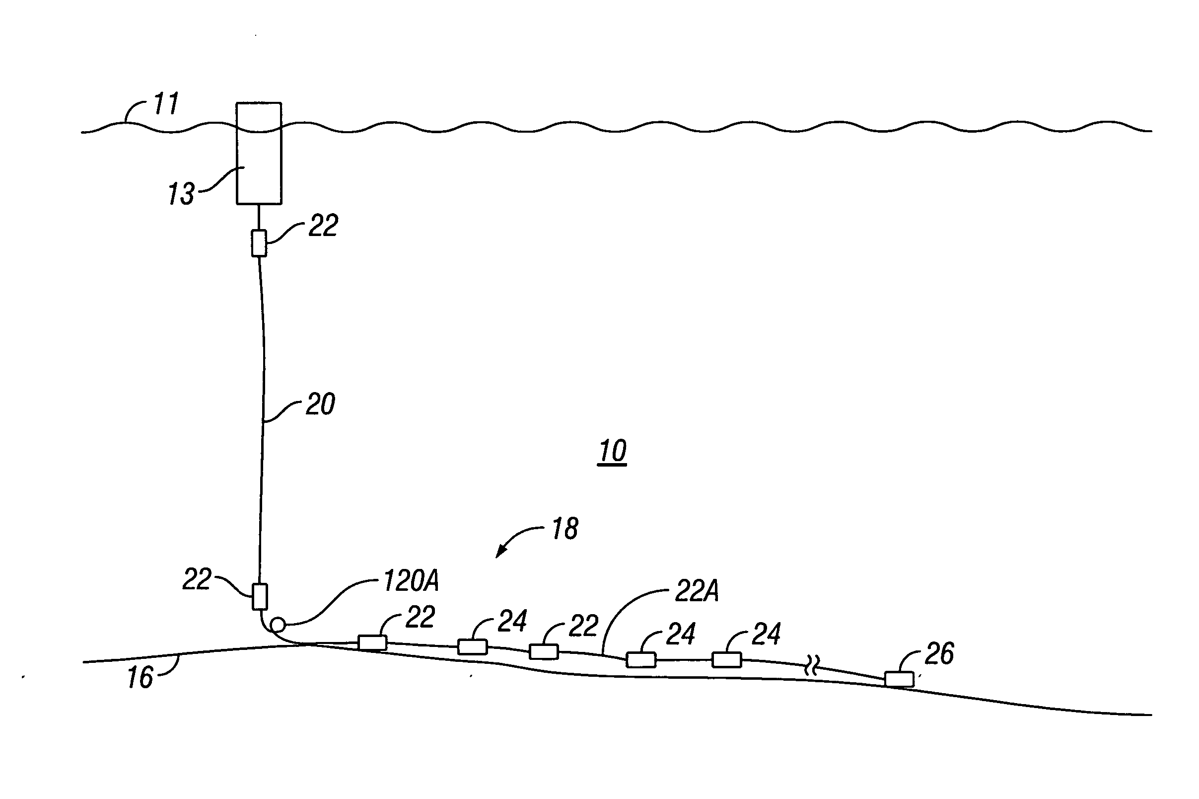
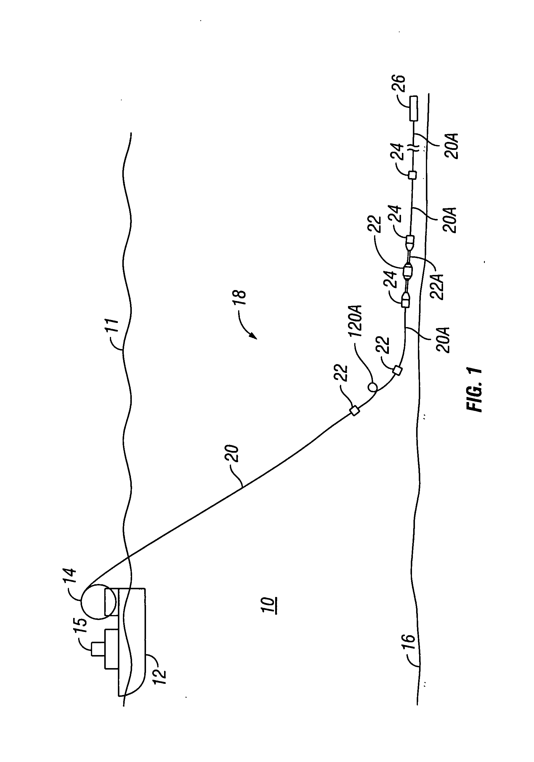
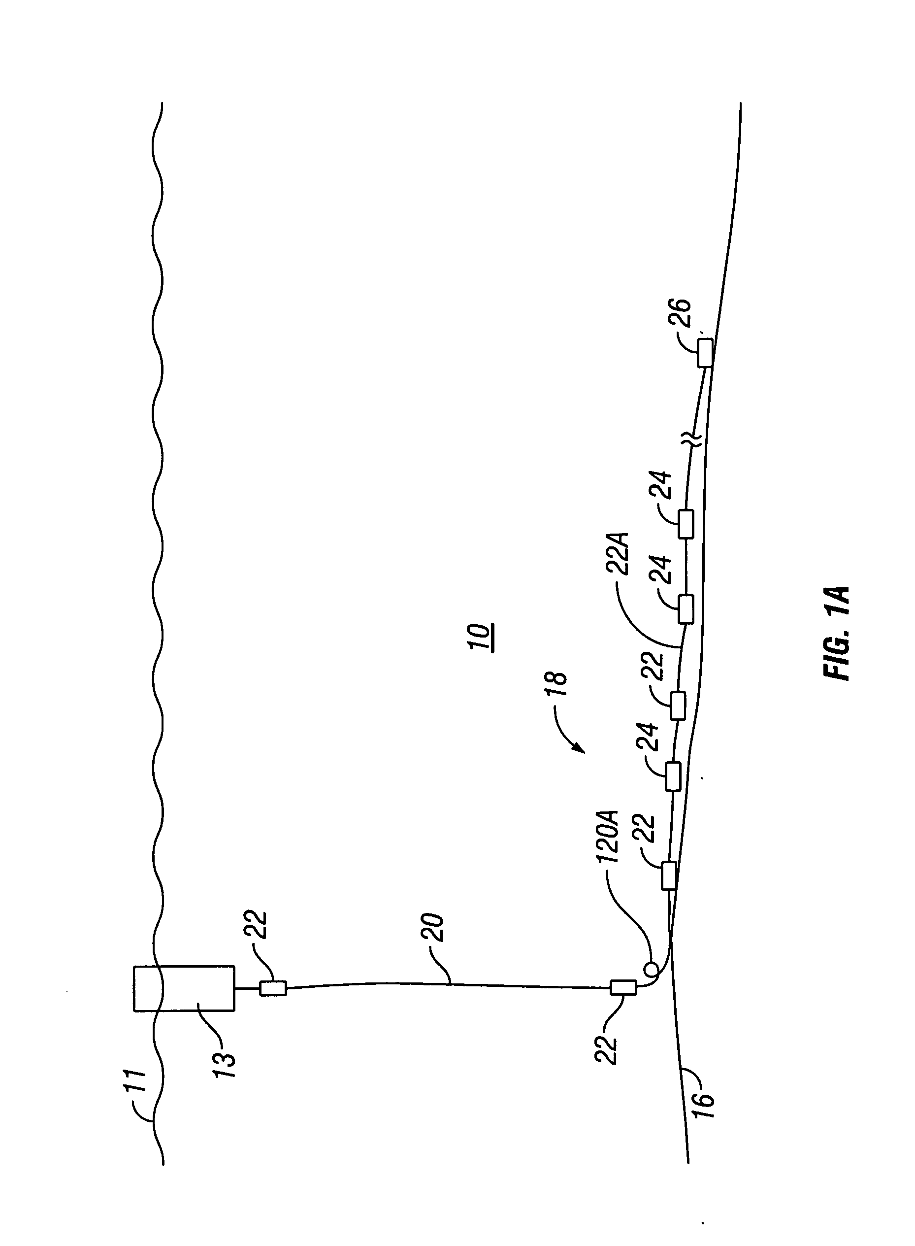
The invention is a system for collecting data from the ocean floor using a cable system. The cable has seismic sensors at different locations and is connected to a vessel and a buoy at the surface of the water. The cable has a loop of cable at the bottom of the water to compensate for any movement caused by the water. The system also has swivels to allow for rotation and transmission of force along the cable. The technical effect of this invention is a more accurate and reliable way to collect data from the ocean floor.

Problems solved by technology

However, there is a tendency of such shallower depth OBCs to assume the shape of the winch or reel while on the winch and under tension.
In such cases, the loops may cause the OBC to kink when tension is reapplied.
Kinking may damage the cable, thus necessitating expensive repair or replacement of the cable and shutting down the operation.
Such stress relief generates substantial torque imbalance along the cable at the water bottom and at the water column interface.
The loops can cause the cable to kink when the cable is retrieved from the water bottom.
Lateral movement of the recording vessel imparts lateral tension along the connected OBCs and causes the cable to ‘roll’ along the water bottom Such lateral movement is another source of torque which may result in kinks in the OBCs.
Just as in the case of the single OBC survey operation, when an OBC having loops therein is retrieved, the rapid application of axial stress may result in kinks in the cable as the torque along the loop cannot be quickly relieved.

Method used


Image

  • Ocean bottom seismic sensor cable system including torque-relieveing swivel
  • Ocean bottom seismic sensor cable system including torque-relieveing swivel
  • Ocean bottom seismic sensor cable system including torque-relieveing swivel

Examples


Embodiment Construction

[0024] One example of an ocean bottom cable (OBC) system is shown in FIG. 1 being deployed in a body of water 10. A cable handling vessel 12, which may in some examples include seismic data recording equipment 15 of any type known in the art, moves in a selected direction along the surface 11 of the water 10. A winch, reel or similar spooling device, shown generally at 14, is disposed on the cable handling vessel 12 such that an OBC system 18 can be deployed from the cable handling vessel 12, typically from its aft end under a predetermined tension. The winch 14 can be any type known in the art for deployment of marine seismic sensor cables. The winch 14 has the OBC system 18 spooled thereon. The winch 14 extends the OBC system 18 into the water 10 as the cable handling vessel 12 moves along the selected direction. The rate of unspooling and the speed of the cable handling vessel 12 are selected such that a sensor cable portion of the OBC system 18 eventually rests on the water bott...


PUM


Abstract

An ocean bottom cable system includes a sensor cable configured to be extended from a vessel to the bottom of the body of water. The sensor cable includes a plurality of seismic sensor units at spaced apart locations. A lead in cable is coupled at a to at least one of the vessel and a buoy, and to an aft lead in cable segment. The segment includes a cable loop to compensate water-caused motion of the lead in cable substantially without moving the sensor units. A first swivel is disposed between a forward end of the sensor cable and an aft end of the aft lead in cable segment. The first swivel enables relative rotation between the sensor cable and the segment. At least a second swivel is disposed between the second end of the lead in cable and a forward end of the aft lead in segment.

Description

CROSS-REFERENCE TO RELATED APPLICATIONS [0001] This application is a continuation-in-part of U.S. patent application Ser. No. 11 / 082,264 filed on Mar. 17, 2005, which is copending herewith.STATEMENT REGARDING FEDERALLY SPONSORED RESEARCH OR DEVELOPMENT [0002] Not applicable. BACKGROUND OF THE INVENTION [0003] 1. Field of the Invention [0004] The invention relates generally to the field of ocean bottom cable (OBC) seismic survey sensor systems. More specifically, the invention is related to devices for improving the efficiency of deployment and retrieval of OBCs, and for reducing the incidence of damage to OBCs during deployment and retrieval and during periods of operation in high sea states. [0005] 2. Background Art [0006] Seismic surveying performed in bodies of water (marine seismic surveying), such as lakes or the ocean, includes ocean bottom cable (OBC) surveying techniques. OBCs are deployed on the water bottom and include seismic sensors arranged such that various techniques ...

Claims


Application Information

Patent Timeline
Patent Type & Authority Applications(United States)
IPC IPC(8): G01V1/38
CPCH02G1/10G01V1/201G01V1/38G01V1/3817
Inventor GEORGE, NICHOLAS C.SEMB, OLE-FREDRIK
Owner PGS GEOPHYSICAL AS
Learn More