
Secondary battery module

a battery module and secondary battery technology, applied in the field of secondary battery modules, can solve the problems of high cost of electric sources, complicated connection work of electric sources, and high man-hours, and achieve the effect of excellent vibration resistan

Inactive Publication Date: 2008-03-06
HITACHI AUTOMOTIVE SYST LTD
View PDF7 Cites 58 Cited by
  • Summary
  • Abstract
  • Description
  • Claims
  • Application Information

AI Technical Summary

Benefits of technology

[0010]In view of the above circumstances, an object of the present invention is to provide a secondary battery module which is excellent in vibration resistance.
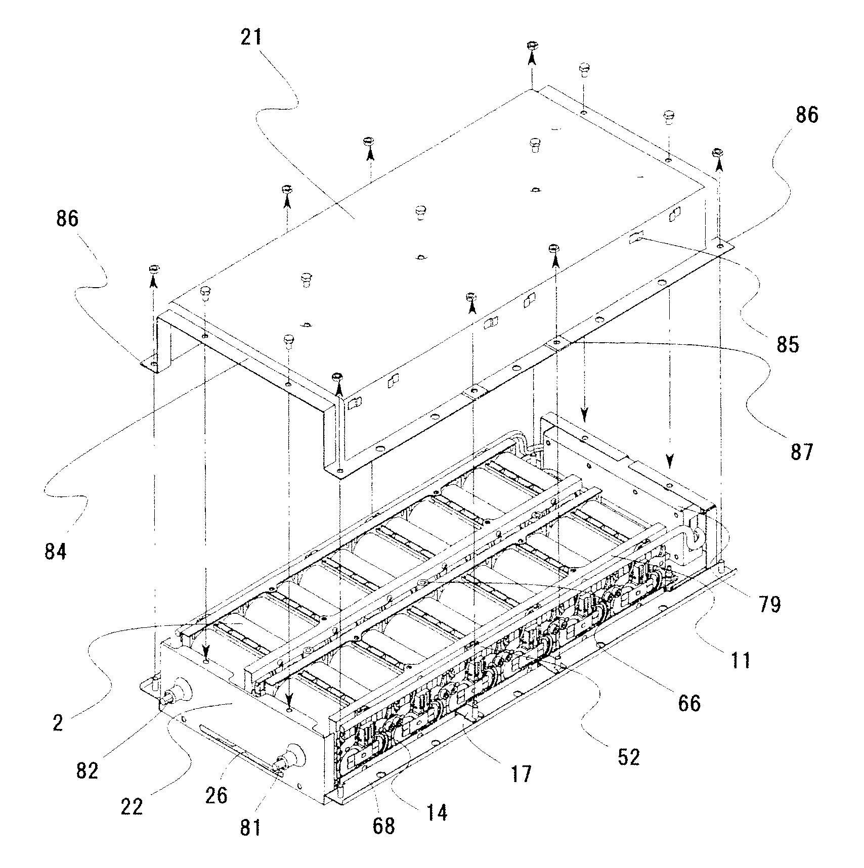
[0012]According to the present invention, since the unit cell groups are held and fixed by two channel shaped block bases which support a lower portion thereof and two channel shaped block reinforcing plates which hold an upper portion thereof, the unit cell groups do not move freely even if vibration is added to the battery block; and since an elastic body is laid between the block bases and the unit cell groups, a space derived due to variance in size accuracy of frames which hold and fix the unit cells and derived due to variance in size accuracy of the block bases can be removed, thereby vibration resistance is enhanced.

Problems solved by technology

Work for connecting the several tens unit cells in series with the conductive members requests a lot of man-hours, which makes the electric source costly in view of preventing short cuts.
Connecting work thereof is also complicated.
But, when one of the connected unit cells has some trouble, all of the connected several tens of unit cells become inferior goods.
However, because this method increases the number of parts, it causes problems of parts cost, manufacturing cost, weight increase and the like.
Thus, a space between parts is subject to receiving influence of vibration, which may cause a problem of destruction of connecting parts, stop of power supply due to destruction of insulation parts, generation of heat or catching of fire due to a short circuit, or the like.
Further, a problem of recycling (disassembling of the battery module) which is in general more complicated than assembling be also considered.

Method used


Image

  • Secondary battery module
  • Secondary battery module
  • Secondary battery module

Examples


Embodiment Construction

[0022]With reference to the drawings, an embodiment where the present invention is applied to a secondary battery module for an electric vehicle will be explained below.

[0023](Constitution)

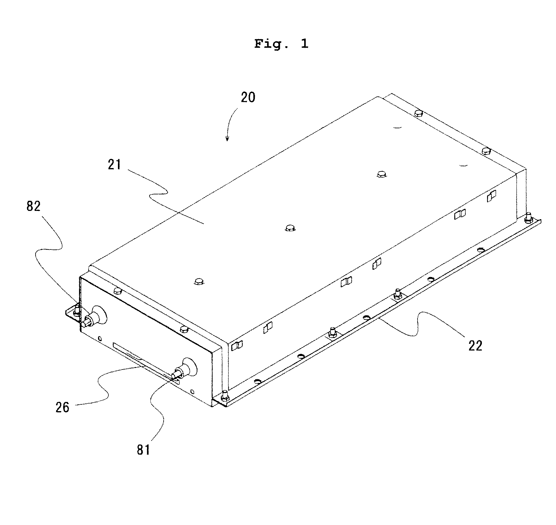
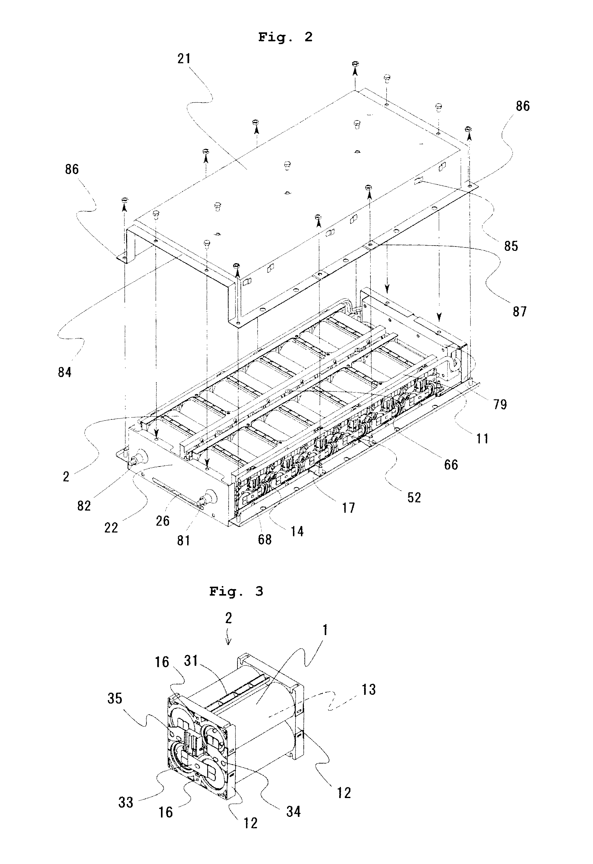
[0024]As shown in FIG. 1 and FIG. 2, a battery module 20 in this embodiment is provided with an exterior case formed in an approximately hexahedral shape made of metal and composed of an upper lid 21 and a lower lid 22. A plurality of assembled batteries 2, each being served as a unit cell group, are accommodated and fixed in the exterior case. There are wires (lines) for detecting voltages of unit cells which constitute the assembled battery 2 and a controlling circuit in the exterior case. These parts are protected by the exterior case from external electric noises.

[0025]

[0026]In the assembled battery 2, as shown in FIG. 3, a plurality of unit cells 1 are arranged in two rows and two columns such that their polarities become alternate and the plurality of the unit cells 1, preferably 4 unit cell...


PUM

PropertyMeasurementUnit
elasticaaaaaaaaaa
adhesionaaaaaaaaaa
unit cellaaaaaaaaaa

Abstract

The present invention provides a secondary battery module which is excellent in vibration resistance. A battery module 20 has assembled battery blocks 11 each constituted by screw-fixing the assembled batteries 2 to the block bases 3, 4 supporting a lower portion thereof and the two block reinforcing plates 5 supporting an upper portion thereof, the six assembled batteries 2 are sandwiched by and fixed firmly to the block bases 3, 4 and the block reinforcing plates 5. The assembled batteries 2 do not move freely even if vibration is added to the battery module 20. Because the elastic sheet 9 is laid between the block bases 3, 4 and the assembled batteries 2, since a space derived due to variance in size accuracy of frames 12 which hold and fix the unit cells 11 and derived due to variance in size accuracy of the block bases 3, 4 can be removed, and vibration resistance can be enhanced. To thermal stress change caused due to combination of different materials, influence thereof can be reduced by laying the elastic sheet 9.

Description

FIELD OF THE INVENTION[0001]The present invention relates to a secondary battery module, and in particular to a secondary battery module comprising a battery block that a plurality of unit cell groups is disposed adjacently.DESCRIPTION OF THE RELATED ART[0002]A battery power supply apparatus using secondary batteries is structured to have high voltage or high capacity by connecting a plurality of unit cells electrically in series or rows. In order to realize such serial or parallel connection, a technique that a bus bar which is a conductive member is welded to a unit cell, or a technique that a screw portion manufactured in advance is formed respectively at positive and negative electrodes positioned at unit cell ends or a conductive material having the screw portion manufactured in advance is welded or connected to respective of positive and negative electrodes positioned at unit cell ends to fasten the bus bar to the screw portion, has been disclosed. Incidentally, in a unit cell...

Claims


Application Information

Patent Timeline
Patent Type & Authority Applications(United States)
IPC IPC(8): H01M2/24H01M50/529H01M50/213H01M50/264H01M50/271
CPCH01M2/1022H01M2/105H01M2/1077H01M6/42H01M10/5073H01M10/5004H01M10/5016H01M10/503H01M10/5065H01M10/0481H01M10/625H01M10/643H01M10/6566H01M10/613H01M10/6562Y02E60/10H01M50/213H01M50/264H01M50/271
Inventor ONUKI, TOSHIAKIAIBA, TUNEMIGOTO, TAKEYUKIONO, TATSUO
Owner HITACHI AUTOMOTIVE SYST LTD
Learn More