
Meter jaw assembly

a technology of meter jaws and assemblies, applied in the direction of coupling device details, coupling device connections, electric discharge lamps, etc., can solve the problems of increasing assembly costs, high number of components, and reducing reliability, so as to reduce the number of components, reduce the number of manufacturing operations, and reduce the heat generated in the meter jaws

Active Publication Date: 2008-03-06
MILBANK MFG
View PDF4 Cites 7 Cited by
  • Summary
  • Abstract
  • Description
  • Claims
  • Application Information

AI Technical Summary

Benefits of technology

[0010]The present invention provides greatly improved watt-hour meter socket components and assemblies thereof which reduce the number of components required for each meter jaw in a meter socket, which reduce the number of manufacturing operations required to manufacture the electrical connector used in each meter jaw, which reduce the heat generated in each meter jaw in a meter socket, and which minimize the thermal gradient from the meter jaw to the power connection.
[0013]In a mold-in embodiment of the meter jaw assembly, the meter jaw mounting key is a mold-in mounting key, formed by a key web extending from the base tab with a plurality of key flanges extending from opposite sides of the key web to form substantially serrated surfaces on the opposite sides of the key web. A pair of the mold-in meter jaw members are positioned in spaced relation within a mounting block mold with the mold-in mounting key extending into the mounting block mold cavity. The meter jaw members are properly positioned and oriented to align the meter blade receiving spaces. A resin in a plastic state is injected into the mold cavity and allowed to solidify or cure whereby parts of the pair of meter jaw members are molded into the mounting block to simplify forming a meter socket assembly half.

Problems solved by technology

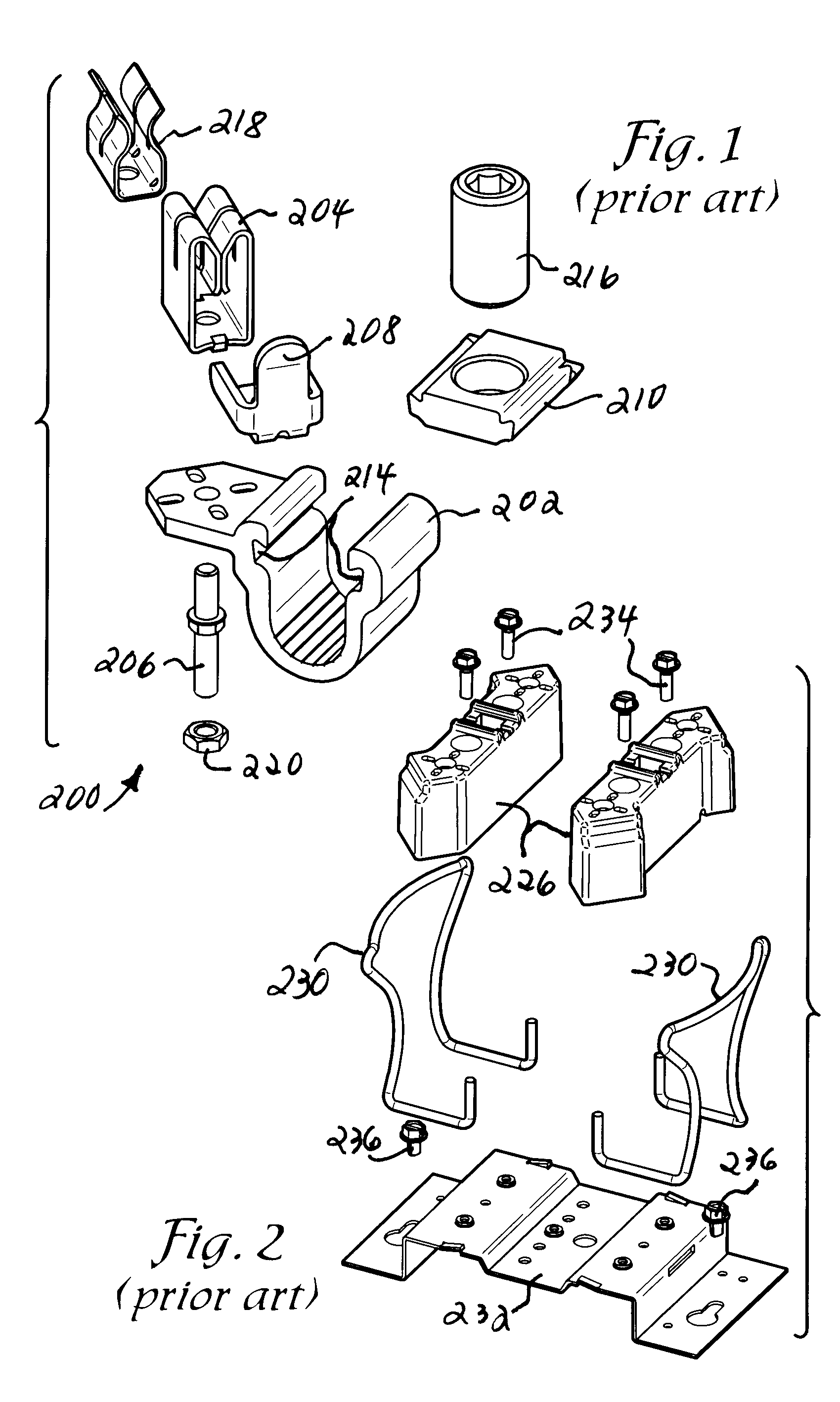
Firstly, the use of a high number of components acts to reduce reliability.
Secondly, the high number of components acts to increase assembly costs.
Yet another disadvantage of the current art is the temperature rise permitted.
These and other electronic components exhibit reduced life phenomena at increased temperatures.

Method used


Image

  • Meter jaw assembly
  • Meter jaw assembly
  • Meter jaw assembly

Examples


Embodiment Construction

[0031]As required, detailed embodiments of the present invention are disclosed herein; however, it is to be understood that the disclosed embodiments are merely exemplary of the invention, which may be embodied in various forms. Therefore, specific structural and functional details disclosed herein are not to be interpreted as limiting, but merely as a basis for the claims and as a representative basis for teaching one skilled in the art to variously employ the present invention in virtually any appropriately detailed structure.

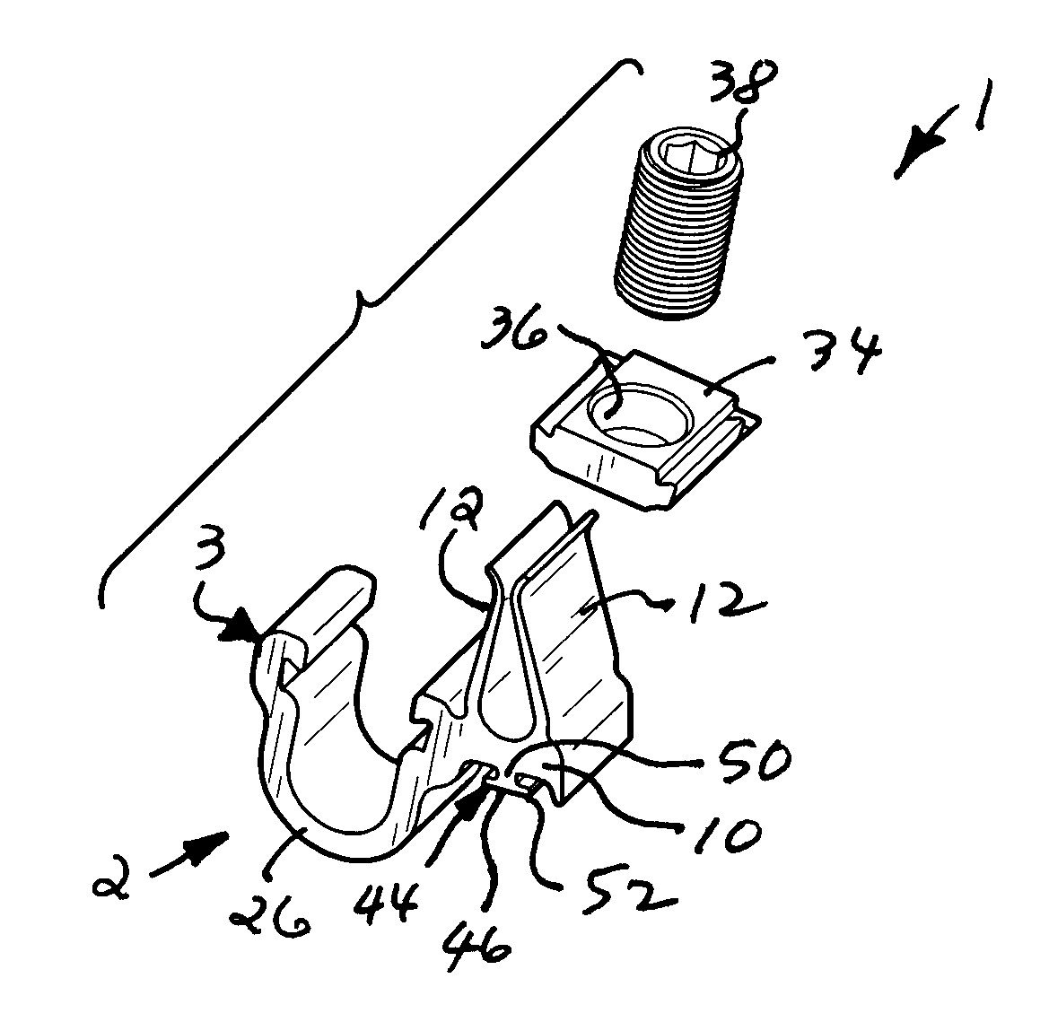
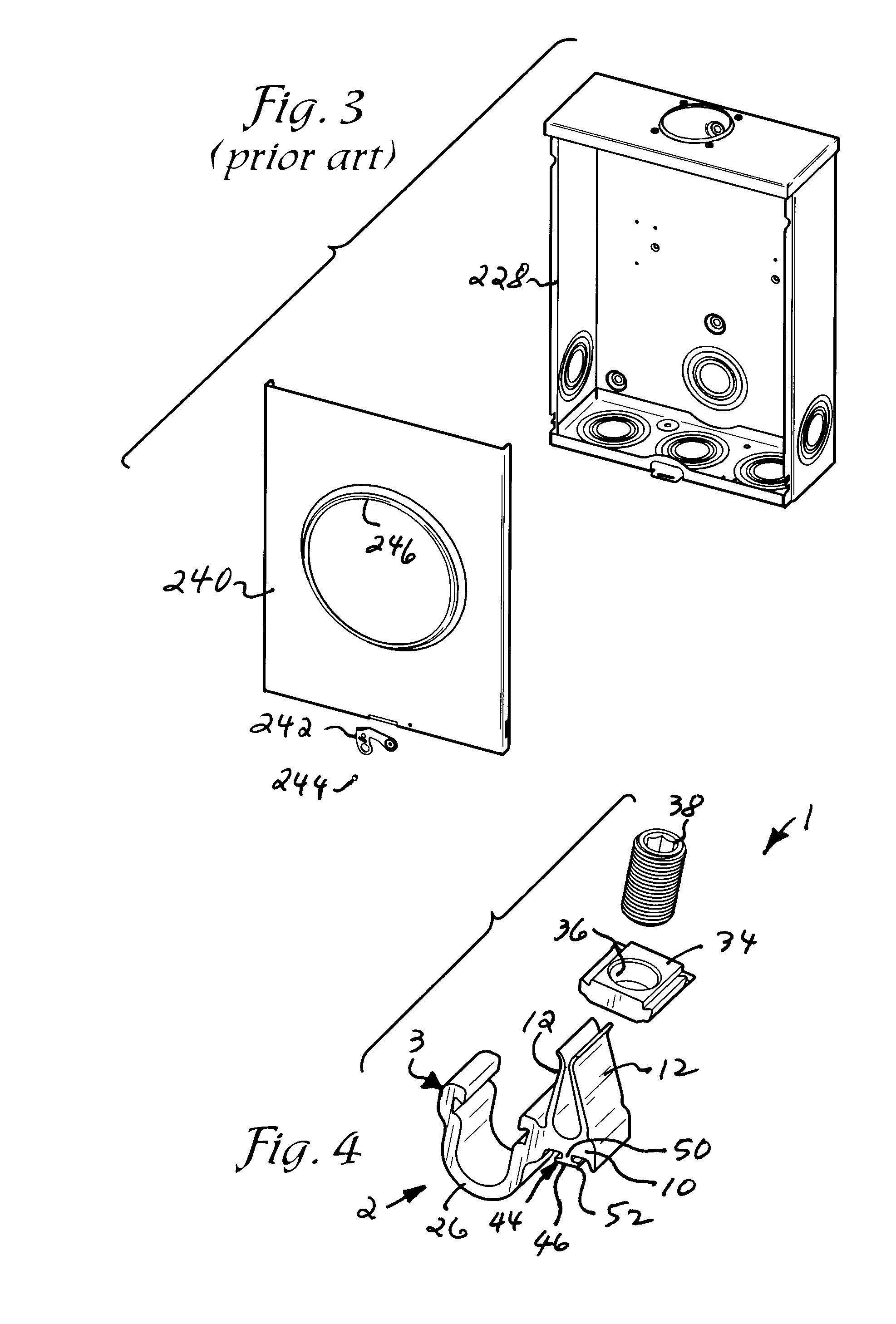
[0032]Referring drawings in more detail, the reference numeral 1 generally designates an improved watt-hour meter jaw assembly according to the present invention. Sets of the jaw assemblies 1 are used to receive corresponding sets of connector blades (not shown) of electrical power industry standard configurations of watt-hour meters. The meter jaw assemblies 1 may include one of two principal embodiments of meter jaw members 2, including a slide-in meter jaw...


PUM


Abstract

An improved meter jaw assembly includes a one-piece meter jaw member formed by extrusion and including a pair of resilient jaw contacts extending from a base tab which also has a U-shaped wire receiver extending therefrom. Inner surfaces of the receiver are grooved to receive a slide nut with a threaded slide screw to clamp the end of a power cable therein. The jaw members include mounting keys to secure them to a mounting block. In a mold-in embodiment of the assembly, a pair of jaw members have mounting keys molded into the mounting block. In a slide-in embodiment, a pair of jaw members are retained in slide-in channels within the mounting block.

Description

CROSS-REFERENCE TO RELATED APPLICATION [0001]This application claims priority under 35 U.S.C. 119(e) and 37 C.F.R. 1.78(a)(4) based upon copending U.S. Provisional Application, Ser. No. 60 / 842,125 for AN IMPROVED METER JAW ASSEMBLY, filed Sep. 1, 2006, which is incorporated herein by reference.BACKGROUND OF THE INVENTION[0002]The present invention relates generally to contact assemblies, and more particularly, to a one-piece meter jaw and to meter socket assemblies incorporating such jaws, such as for use in a socket for a direct-reading watt-hour meter. This type of socket is known in the trade as an “S” type meter socket. It has a standardized form to allow the interchangeability of meters from various manufacturers without removing any wires or cables. A watt-hour meter having a typical pattern of a pair of parallel sets of aligned connector blades is shown in U.S. Pat. No. 4,104,588, which is incorporated herein by reference. While such a meter socket is employed for meters capa...

Claims


Application Information

Patent Timeline
Patent Type & Authority Applications(United States)
IPC IPC(8): H01R4/48
CPCH01R4/36H01R13/112H01R9/2491H01R9/2458
Inventor SIGLOCK, JOHN V.GLASGOW, SHAWN J.
Owner MILBANK MFG
Learn More