
Control of receiver antenna diversity

a technology of receiver antenna diversity and control, applied in diversity/multi-antenna systems, power management, wireless communication, etc., can solve the problems of increasing power consumption, shortening operation time, and increasing power consumption

Active Publication Date: 2008-03-06
NOKIA TECHNOLOGLES OY
View PDF2 Cites 9 Cited by
  • Summary
  • Abstract
  • Description
  • Claims
  • Application Information

AI Technical Summary

Benefits of technology

[0004]The present invention seeks to provide improved apparatuses, user radio terminals, a method, and a computer program.

Problems solved by technology

However, radio receivers utilizing receiver antenna diversity are more complex than single-antenna receivers.
This increases power consumption.
Especially in a user radio terminal provided with a battery or other similar independent energy source the increased power consumption may shorten operation time.

Method used


Image

  • Control of receiver antenna diversity
  • Control of receiver antenna diversity

Examples


Embodiment Construction

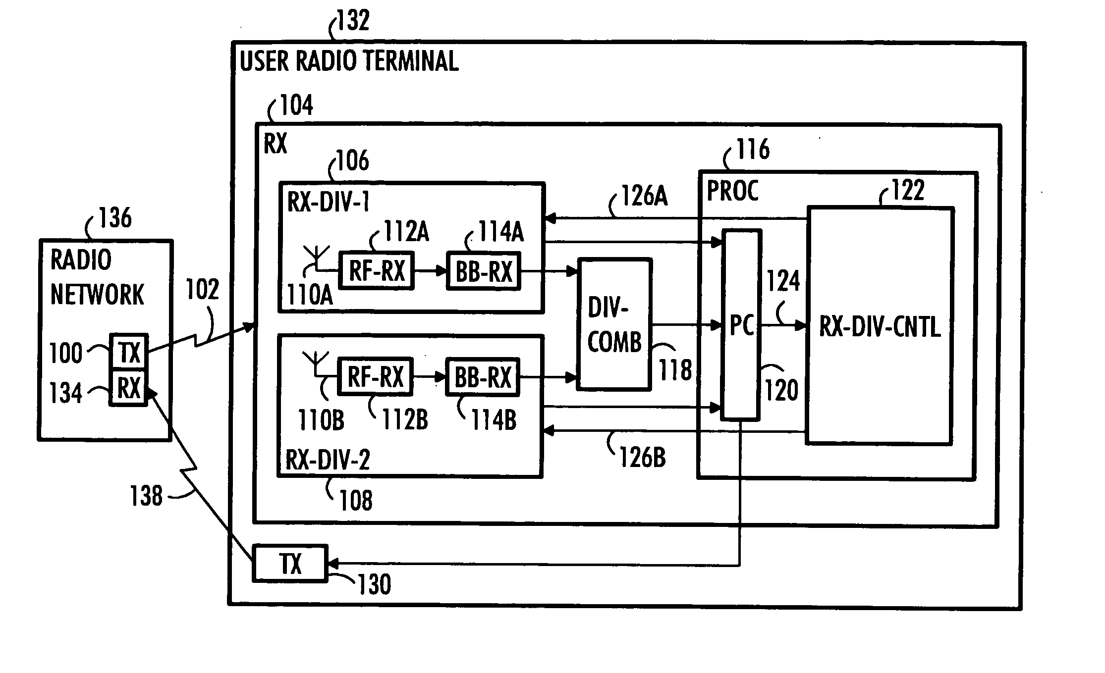
[0014]With reference to FIG. 1, let us examine embodiments of a radio receiver 104. The radio receiver 104 utilizes the receiver antenna diversity technique, in which a radio signal 102 is received using multiple receiver antennas 110A, 110B. A transmitter 100 transmitting the radio signal 102 may utilize multiple transmitting antennas, but it is not necessary. A diversity combining unit 118 combines the signals from different receiver antennas 110A, 110B to produce a signal of improved quality. The basic receiver antenna diversity technique is also known as space diversity, in which multiple versions of the transmitted radio signal propagated on different paths are received. Also other diversity techniques may be utilized, such as polarization diversity, time diversity and frequency diversity, but they are not necessary. The radio receiver 104 may be utilized in a number of different systems, for example in a CDMA (Code Division Multiple Access) or WCDMA (Wideband CDMA) system, or ...


PUM


Abstract

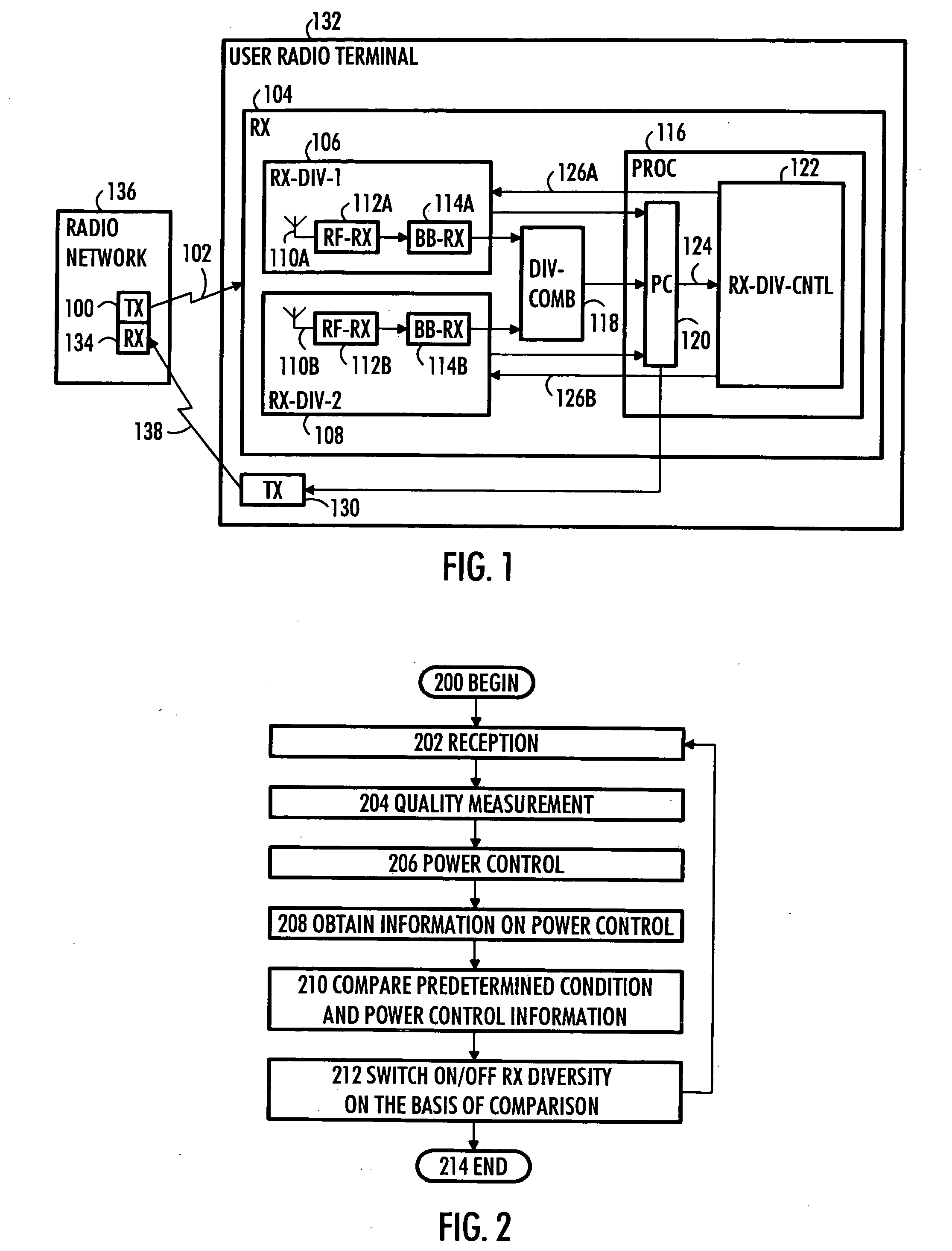
Control of receiver antenna diversity is described in relation to apparatuses, user radio terminals, a method, and a computer program. The apparatus comprises an interface configured to obtain information on a power control procedure of a radio receiver and a processing unit configured to switch on / off a receiver antenna diversity branch of the radio receiver on the basis of a comparison between a predetermined condition and the information on the power control procedure.

Description

FIELD[0001]The invention relates to apparatuses, user radio terminals, a method, and a computer program.BACKGROUND[0002]A receiver antenna diversity technique may be utilized in a radio receiver to enhance performance. As multiple samples of a radio signal are obtained using receiver antenna diversity and combined, the desired signal is amplified. In addition, receiver antenna diversity improves network capacity and service coverage.[0003]However, radio receivers utilizing receiver antenna diversity are more complex than single-antenna receivers. This increases power consumption. Especially in a user radio terminal provided with a battery or other similar independent energy source the increased power consumption may shorten operation time.SUMMARY OF THE INVENTION[0004]The present invention seeks to provide improved apparatuses, user radio terminals, a method, and a computer program.[0005]According to an aspect of the present invention, there is provided an apparatus as specified in ...

Claims


Application Information

Patent Timeline
Patent Type & Authority Applications(United States)
IPC IPC(8): H04B7/00H04Q7/20H04W52/42
CPCH04B7/0602H04W52/42H04B7/0802H04B7/0808H04W52/241H04W52/247H04W52/248
Inventor KOMULAINEN, PETRITIMISJARVI, RISTO
Owner NOKIA TECHNOLOGLES OY
Learn More