Ultrasonic wound debrider probe and method of use

a technology of ultrasonic wound debrider and probe, which is applied in the field of ultrasonic surgical instruments, can solve the problems of operator fatigue and patient discomfort, prolonging the length of the procedure, and less effective eschar buildup of bluet straight probes when wound healing

Active Publication Date: 2008-03-06
MISONIX INC
View PDF11 Cites 166 Cited by
  • Summary
  • Abstract
  • Description
  • Claims
  • Application Information

AI Technical Summary

Benefits of technology

[0010]It is an additional object of the present invention to provide an improved ultrasonic surgical instrument that may be used in debriding deep wounds such as cuts and puncture wounds.

Problems solved by technology

However, in applications such as the debridement of burns, wounds, diabetic ulcers or ulcers induced by radiation treatments, the blunt straight probe has been shown to be less effective in removing the hard eschar buildup that occurs when the wound is healing.
This extends the length of the procedure and causes operator fatigue and patient discomfort.

Method used


Image

  • Ultrasonic wound debrider probe and method of use
  • Ultrasonic wound debrider probe and method of use

Examples


Embodiment Construction

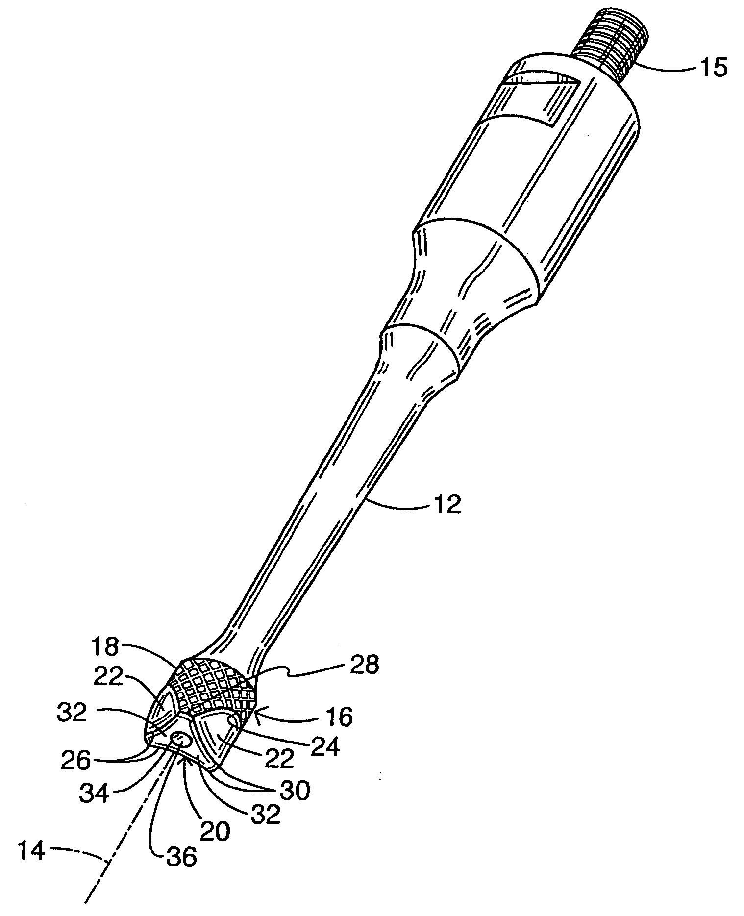
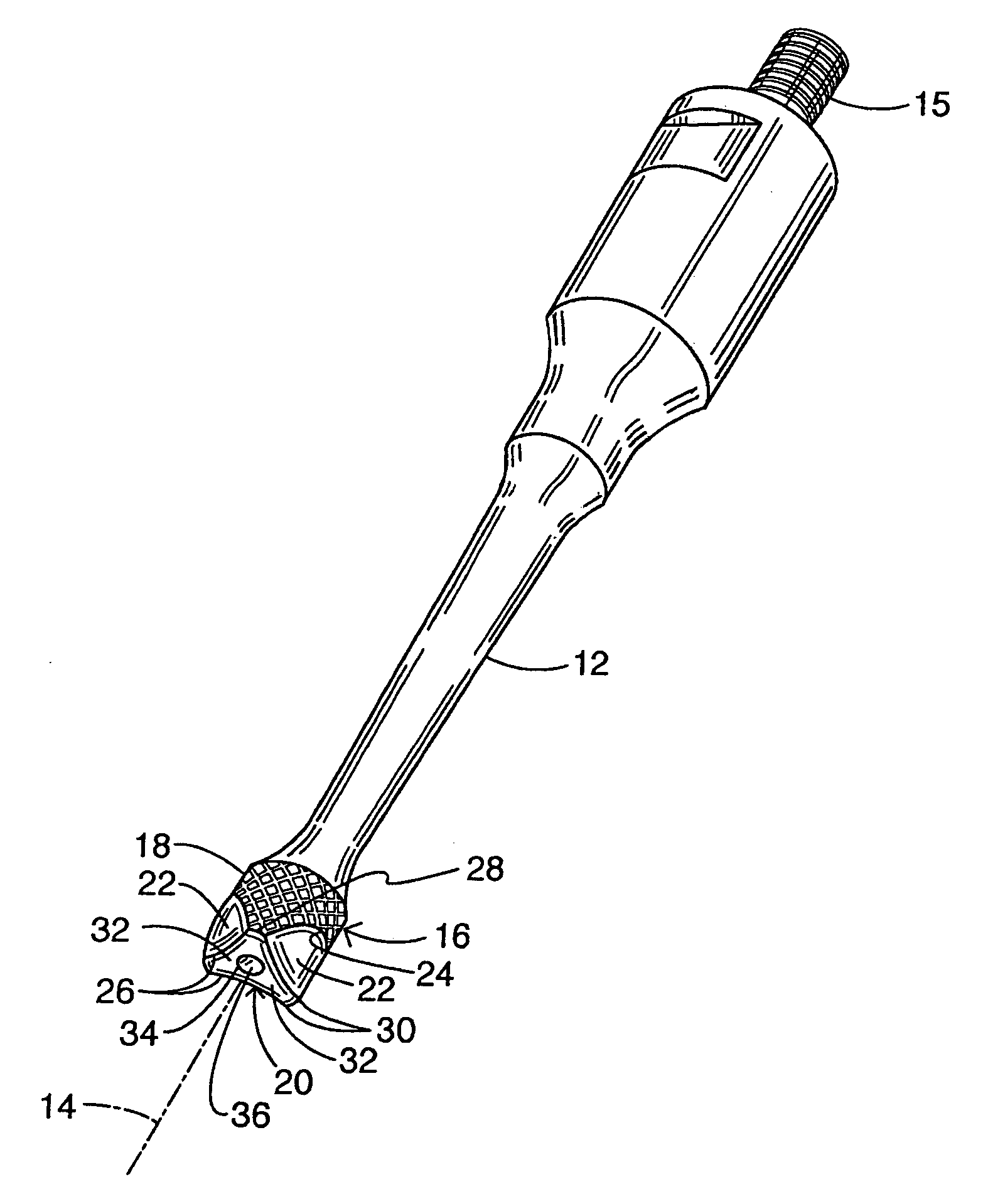
[0022]An ultrasonic probe as shown in the drawing includes a shaft 12 having a longitudinal axis 14. At a proximal end of the shaft is provided a screw-type connector 15 for coupling the probe to an ultrasonic transducer assembly in a handpiece (neither shown). A cylindrical or barrel-shaped head 16 is disposed at a distal end of shaft 12. Head has a knurled cylindrical lateral surface 18 and an end face 20 oriented transversely or perpendicularly to axis 14. Head 16 is formed with three concave shaping surfaces 22 at a distal end of lateral surface 18. Each of the shaping surfaces extends at a respective acute angle to axis 14. Accordingly, each shaping surface 22 is inclined relative to lateral surface 18 and end face 20. Each shaping surface 22 intersects or is contiguous with cylindrical surface 18 along an arcuate groin line 24. Each shaping surface 22 intersects or is contiguous with end face 20 along a concave edge 26.

[0023]Shaping surfaces 22 are angularly or circumferential...


PUM


Abstract

An ultrasonic probe includes a shaft having a longitudinal axis and a head disposed at a distal end of the shaft. The head has a cylindrical lateral surface and an end face oriented perpendicularly to the axis. The head has three shaping surfaces at a distal end of the cylindrical surface, each shaping surface extending at an acute angle to the axis. Each of the shaping surfaces intersects or is contiguous with both the cylindrical surface and the end face.

Description

BACKGROUND OF THE INVENTION[0001]This invention relates to ultrasonic surgical instruments and associated methods of use. More particularly, this invention relates to high-efficiency medical treatment probes for ultrasonic surgical aspirators. These probes increase the ability to fragment and emulsify hard and soft tissue in a clinical environment while reducing unwanted heat and collateral tissue damage.[0002]Over the past 30 years, several ultrasonic tools have been invented which can be used to ablate or cut tissue in surgery. Such devices are disclosed by Wuchinich et al. in U.S. Pat. No. 4,223,676 and Idemoto et al in U.S. Pat. No. 5,188,102.[0003]In practice, these surgical devices include a blunt tip hollow probe that vibrates at frequencies between 20 kc and 100 kc, with amplitudes up to 300 microns or more. Such devices ablate tissue by producing cavitation bubbles which implode and disrupt cells, by generating tissue compression and relaxation stresses (sometimes called th...

Claims


Application Information

Patent Timeline
Patent Type & Authority Applications(United States)
IPC IPC(8): A61B1/00
CPCA61B17/320068A61B2017/32007
Inventor NOVAK, THEODORE A.D.BUSH, CHRISTOPHER
Owner MISONIX INC
Why Eureka
Try Eureka