AI technical title is built by Patsnap AI team. It summarizes the technical point description of the patent document.
a bandage and phototherapy technology, applied in the field of phototherapy, can solve the problems of patients wearing eye protection, disadvantageous light sources using light banks, and devices without their disadvantages, and achieve the effect of absorbing the stresses commonly placed on the bandag
Inactive Publication Date: 2008-03-06
UNIV OF FLORIDA RES FOUNDATION INC
View PDF11 Cites 54 Cited by
Summary
Abstract
Description
Claims
Application Information
AI Technical Summary
This helps you quickly interpret patents by identifying the three key elements:
Problems solved by technology
Method used
Benefits of technology
Benefits of technology
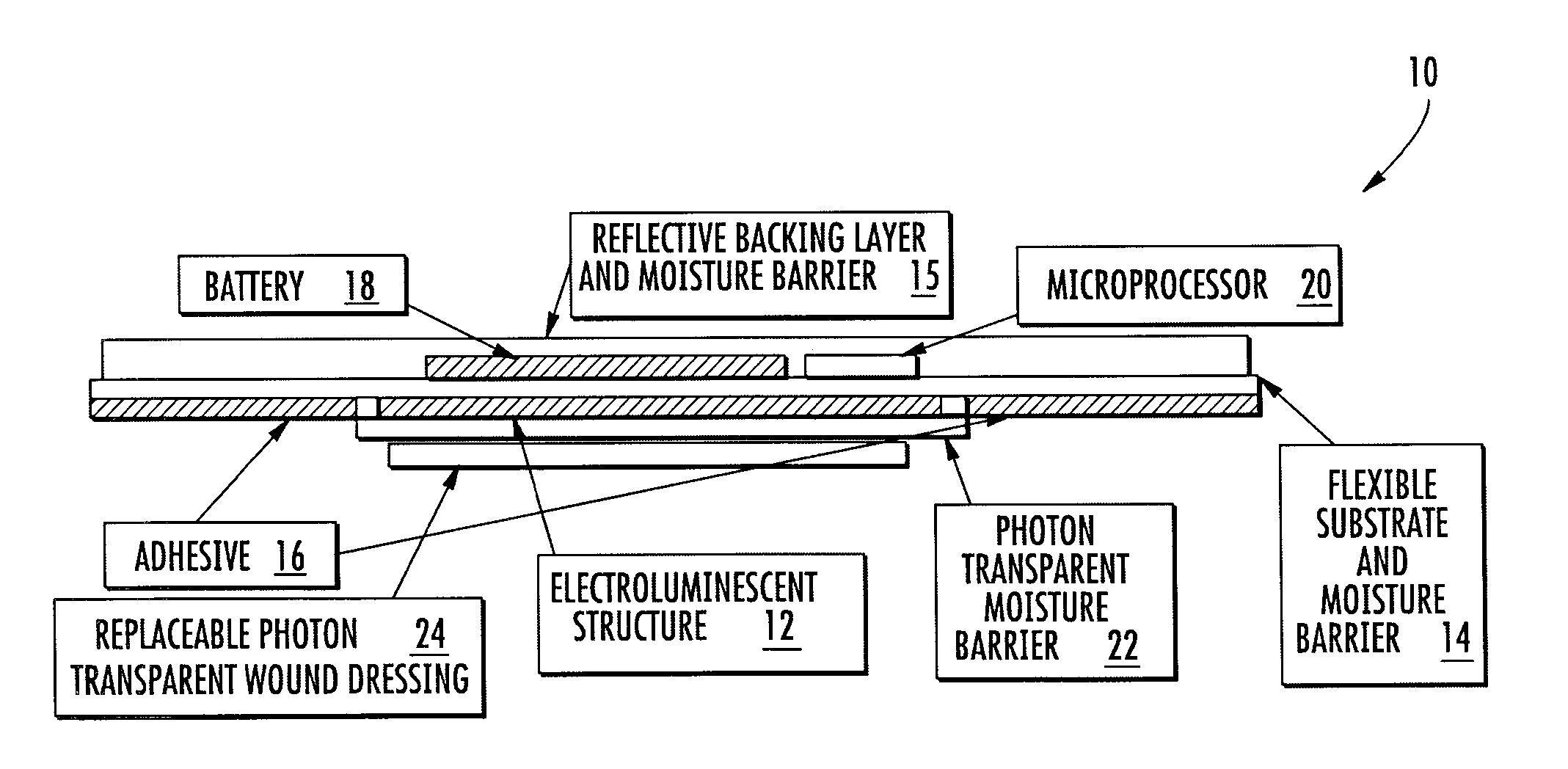
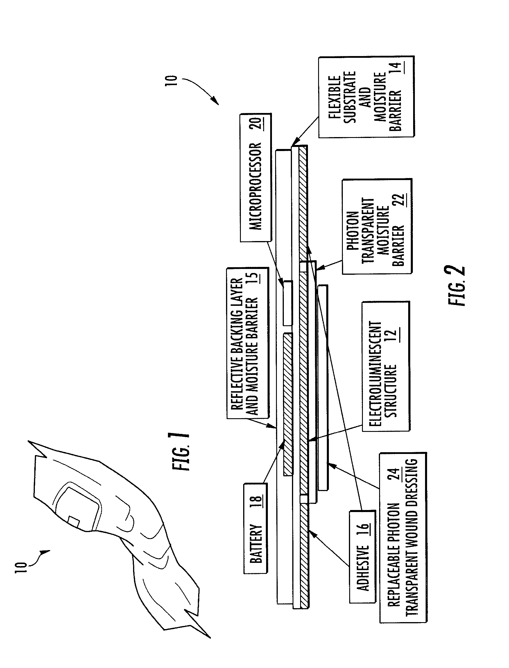
[0014] An advantage of this invention is that the phototherapy bandage is flexible and capable of being attached to a patient to accelerate wound healing and providing pain relief without interfering with the patient's daily activities.
[0027] Another advantage of this invention is that the EL source is rugged and capable of absorbing the stresses commonly placed on a bandage.
Problems solved by technology
While light sources having light banks are still being used, such devices are not without their disadvantages.
For instance, phototherapy devices using light banks require that patients wear eye protection that is often uncomfortable.
Furthermore, these devices are typically large and immobile, which thus, require patients to visit the locations of the light sources each time a dosage is needed.
Light sources using light banks are disadvantageous for at least these reasons.
Fiber optic light sources were developed as a substitute for phototherapy devices containing light banks but have not eliminated all of the drawbacks associated with these devices.
Often times, the geometries of the fiber optic mats are compromised when forces are placed on the fiber optic mats in order to place the fiber optic mats in contact with patients' skin surfaces.
This undesirably results in greater light intensity being concentrated near the light source than at other portions of the fiber optic mat.
Because diffusers are used, the LEDs cannot be placed in contact with a surface.
Thus, the amount of light that an LED emits is not the same amount of light that reaches the surface because a portion of the light produced by the LED is lost when the LED is not placed in contact with a surface.
These conductors significantly add to the overall weight and complexity of the mats.
Use of the plurality of LEDs in such close proximity to each other produces high amounts of heat that can pose potentially dangerous conditions.
Method used
Image
Click on the blue label to locate the original text in one second.
Reading with bidirectional positioning of images and text.
Examples
Embodiment Construction
[0039] The phototherapy bandage 10 of this invention is capable of providing radiation to a localized area of a patient, who may be a human or animal, for accelerating wound healing and pain relief. In addition, phototherapy bandage 10 may also be used for photodynamic therapy and for aesthetic applications. In one embodiment, phototherapy bandage 10 is flexible and capable of being attached to a patient without interfering with the patient's daily routine. Phototherapy bandage 10 may easily conform to the curves of a patient and may come in a variety of exterior shapes and sizes.
[0040] The term “phototherapy”, as used herein is intended to embrace both phototherapy and photodynamic therapy. The term “infrared” as used herein is intended to encompass the range of light spectrum above approximately 650 nm and includes regions often termed “near-infrared” and includes “mid-infrared.”“Transparency” as used herein is defined as passing a substantial portion of light at a wavelength of ...
PUM
Abstract
A phototherapy bandage capable of providing radiation to a localized area of a patient for accelerating would healing and pain relief, photodynamic therapy, and for aesthetic applications. The phototherapy bandage may include a flexible light source that is continuous across the bandage for providing a selected light, such as a visible light, a near-infrared light, or other light, having substantially similar intensity across the bandage. The bandage may also be flexible and capable of being attached to a patient without interfering with the patient's daily routine. The phototherapy bandage may easily conform to the curves of a patient and may come in a variety of exterior shapes and sizes.
Description
CROSS-REFERENCE TO RELATED APPLICATION [0001] This is a continuation application of U.S. application Ser. No. 10 / 732,086, filed Dec. 10, 2003, which is a continuation-in-part of U.S. application Ser. No. 10 / 170,942, filed Jun. 12, 2002, and which claims the priority benefit of U.S. Provisional Application No. 60 / 432,284, filed Dec. 10, 2002.FIELD OF THE INVENTION [0002] The invention is directed generally to phototherapy, and more particularly, to methods and devices for administering radiation to a targeted site on a patient. BACKGROUND [0003] Phototherapy is the therapeutic use of light that has been recognized as an effective method of treating wounds and reducing pain in humans. External phototherapy has been effective in treating various medical conditions, such as, but not limited to, bulimia nervosa, herpes, psoriasis, seasonal affective disorder, sleep disorders, acne, skin cancer, hyperbilirubinemia in infants, and other conditions. Phototherapy is typically administered to...
Claims
Application Information
Patent Timeline
Application Date:The date an application was filed.
Publication Date:The date a patent or application was officially published.
First Publication Date:The earliest publication date of a patent with the same application number.
Issue Date:Publication date of the patent grant document.
PCT Entry Date:The Entry date of PCT National Phase.
Estimated Expiry Date:The statutory expiry date of a patent right according to the Patent Law, and it is the longest term of protection that the patent right can achieve without the termination of the patent right due to other reasons(Term extension factor has been taken into account ).
Invalid Date:Actual expiry date is based on effective date or publication date of legal transaction data of invalid patent.
Patent Type & AuthorityApplications(United States)

