Vacuum Therapy Device

a technology of vacuum therapy and valve, which is applied in the direction of intravenous devices, other medical devices, suction pumps, etc., can solve the problems of increasing the external diameter of the tube connection between the housing and the wound dressing in an undesirable fashion, affecting the treatment effect, and reducing the cost of treatment. , to achieve the effect of optimum patient care, substantial cost savings potential, and reducing the pressur

Inactive Publication Date: 2008-11-13
VCS MEDICAL TECH
View PDF4 Cites 111 Cited by
  • Summary
  • Abstract
  • Description
  • Claims
  • Application Information

AI Technical Summary

Benefits of technology

[0044] This procedure can be used advantageously, for example, to report blockages in the drainage tube. It is also possible with the inventive procedure to determine that the drainage tube is crimped and acts to constrict the pressure. In particular, it is advantageous in this procedure that the wound pressure is measured simultaneously by two different procedures. The direct measurement of wound pressure inside the airtight cover is not influenced by the pressure gradients in the drainage tube influenced by dynamic effects. Conversely, on the other side, the distal pressure on the distal end of the drainage tube is influenced by the dynamic effects in the drainage tube. Measuring both pressure quantities at the same time therefore makes it possible according to the invention to isolate changes in dynamic pressure drops from other effects. That is, if the distal pressur...

Problems solved by technology

A disadvantage of this known wound healing device is that it is relatively complex to provide an additional tube line with the drainage line.
Such a tube generally increases the complexity of the apparatus.
However, this results for example in increasing the external diameter of the tube connection between the housing and the wound dressing in an undesirable fashion.
It also...

Method used


Image

  • Vacuum Therapy Device
  • Vacuum Therapy Device
  • Vacuum Therapy Device

Examples


Embodiment Construction

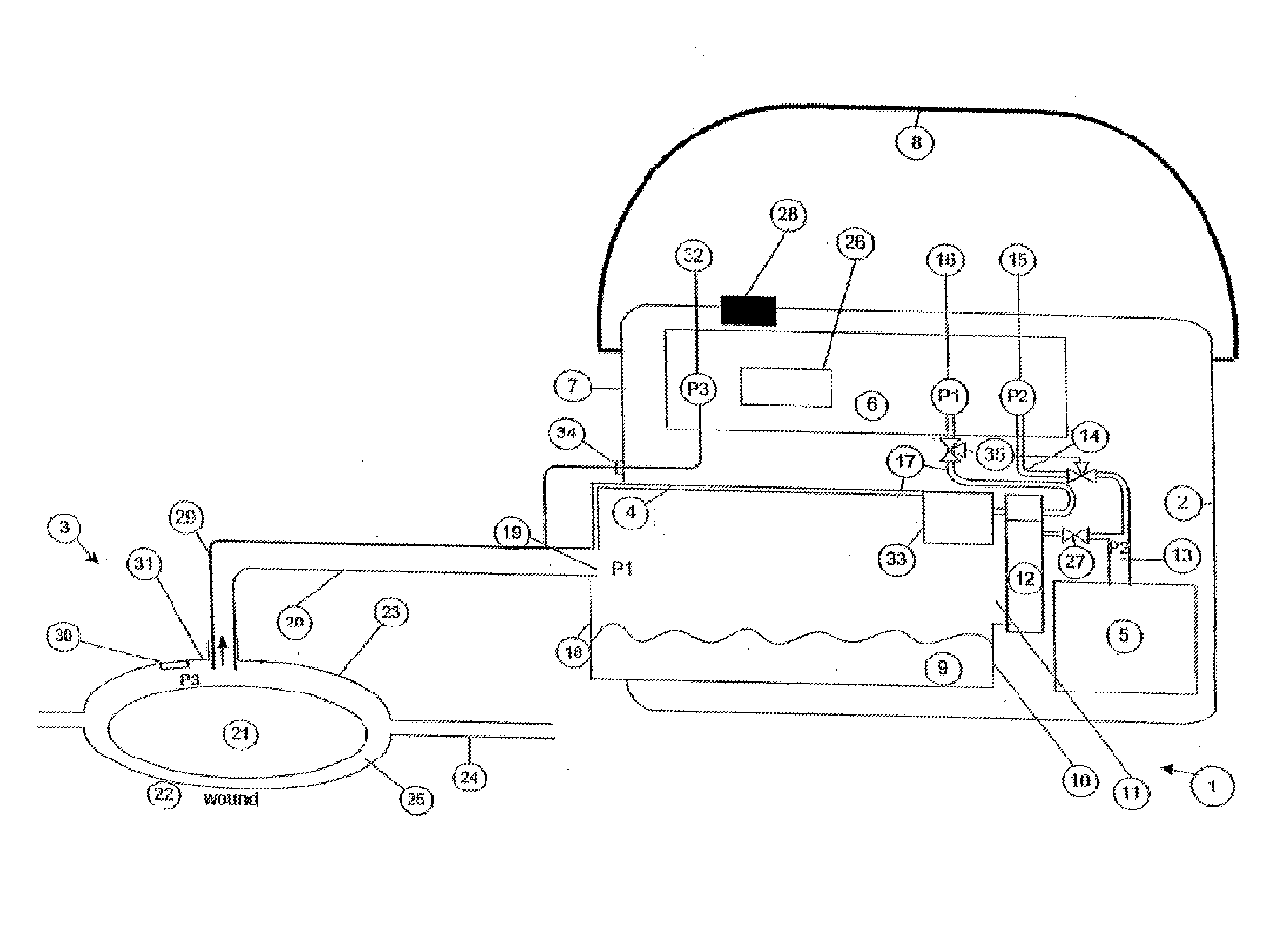
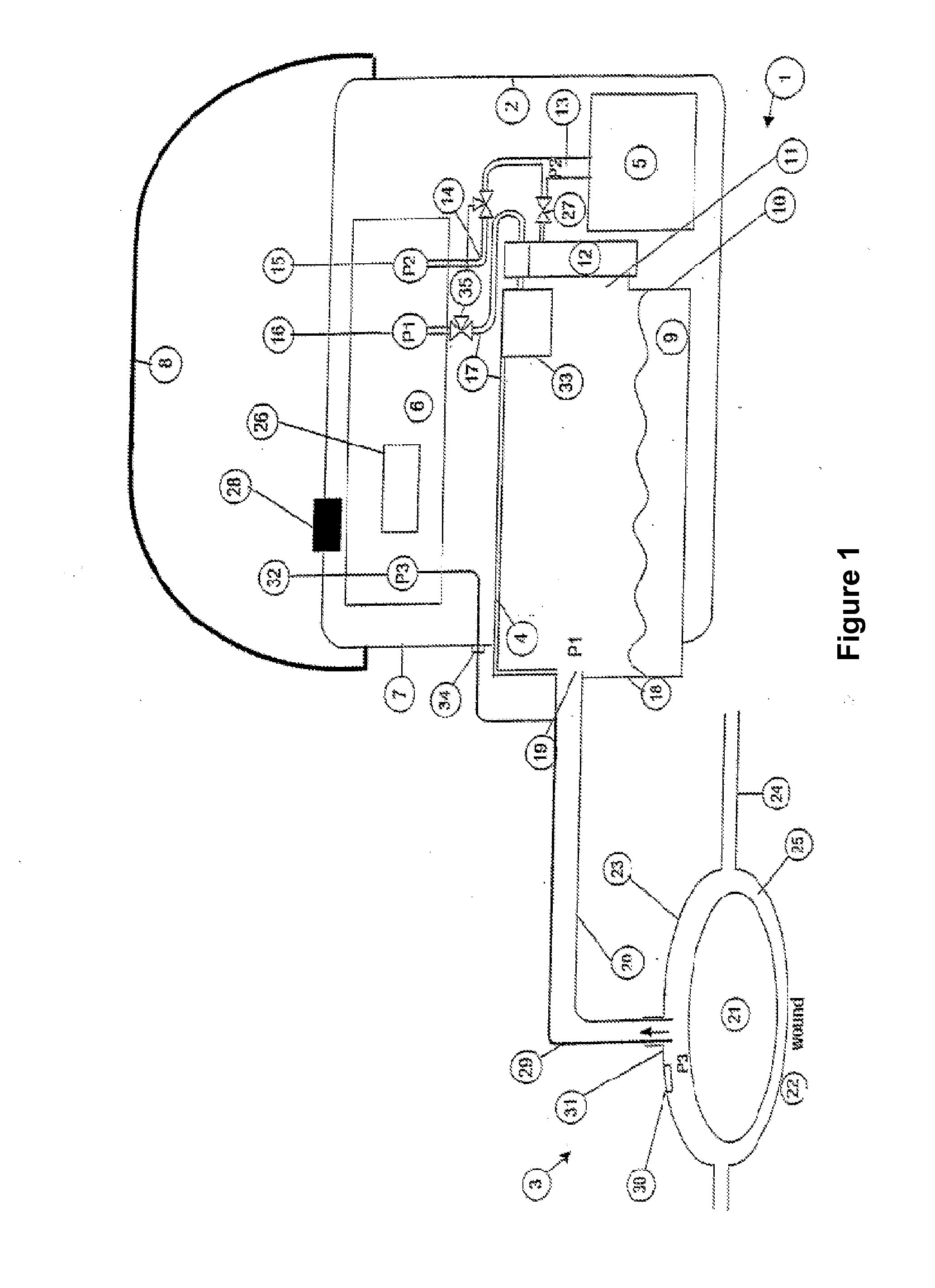
[0051]FIG. 1 schematically shows an embodiment of an inventive wound healing device 1. The wound healing device 1 comprises a base unit 2 and a wound dressing unit 3. The base unit 2 contains a replaceable collecting container 4, a suction pump 5 and a control device 6. The base unit 2 is enclosed by a housing 7. A carrying strap 8 is attached to the housing 7.

[0052] The collecting container 4 contains a mixture 9 consisting of wound exudation and gelling agent. The collecting container 4 comprises a suction opening 11 on one of the inner walls 10 facing the housing 7. The suction opening 11 is connected to the suction pump 5 by the filter 12 and a suction tube 13. A pump-side probe tube 14 branches off from the suction tube 13. The pump-side probe tube 14 carries the prevailing pressure p2 contained in the suction tube 13 to a suction-pump-side pressure sensor 15 which is located in the control device 6. The control device 6 also contains the distal pressure sensor 16, which inter...


PUM


Abstract

The invention relates to a therapeutic device to promote the healing of a wound, comprising a porous paid which is permeable for fluids to place on the wound, a bandage to cover the wound and to provide an essentially airtight seal around the wound, a drainage line connecting the pad with a suction pump so that suction can be applied to the wound to draw the fluids away from it, whereby the line is connected to the suction pump via a canister to collect fluid sucked from the wound, a connector to connect the pad to the drainage line, means to determine a prevailing wound pressure basically comprising the wound and this surrounding skin area, as well as a control unit to control the wound pressure. In order to generally improve metrology with the goal of making possible a more reliable and more secure dressing of the wound, and also to design metrology in an especially simple and error-free way, it is proposed that the pad interconnect the suction pump solely via the drainage line.

Description

CROSS REFERENCE TO RELATED PATENT APPLICATIONS [0001] This application is the National Phase Application under 35 USC §371 of International Application No. PCT / EP2006 / 002623, filed Mar. 22, 2006, which claims priority to German Patent Application 10 2005 014 420.9, filed Mar. 24, 2005.BACKGROUND [0002] A. Technical Field [0003] The present invention relates to a therapeutic device to promote the healing of a wound, comprising: [0004] an essentially airtight cover around the wound, whereby a liquid-permeable pad is preferably provided between the wound and cover, a drainage line connecting the cover with a suction pump, [0005] a drainage line connecting the cover with a suction pump so that the wound can be suctioned to draw fluids from it, whereby a distal end of the drainage line is connected indirectly to the suction pump through a reservoir to collect the fluid suctioned from the wound, [0006] pressure disposal means for the direct or indirect definition of a wound pressure preva...

Claims


Application Information

Patent Timeline
IPC IPC(8): A61M1/00
CPCA61M1/0031A61M1/0066A61M1/0088A61M2205/3344A61M1/743A61M1/80A61M1/882A61M1/96A61M1/912A61M1/984A61M1/966
Inventor MEYER, JOHANNESBAUMANN, DIRK
Owner VCS MEDICAL TECH
Why Eureka
Try Eureka