

Implant system and method to treat degenerative disorders of the spine
a technology of implant system and spine, applied in the field of implant system and method to treat degenerative disorders of the spine, can solve the problems of back pain, difficult and potentially dangerous revision surgery, and subject patients to significant complications
- Summary
- Abstract
- Description
- Claims
- Application Information
AI Technical Summary
Problems solved by technology
Method used
Image

Examples
Embodiment Construction
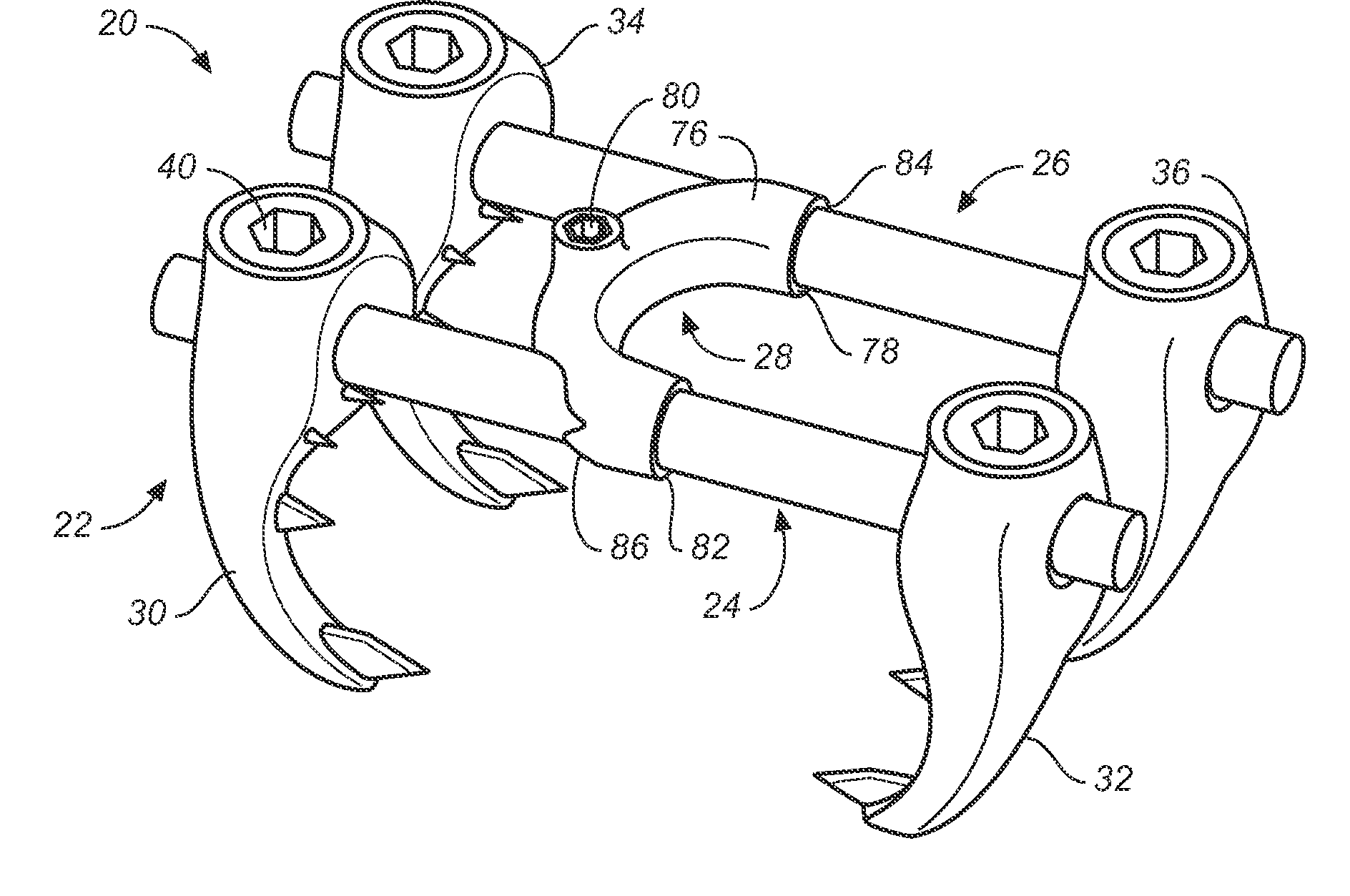
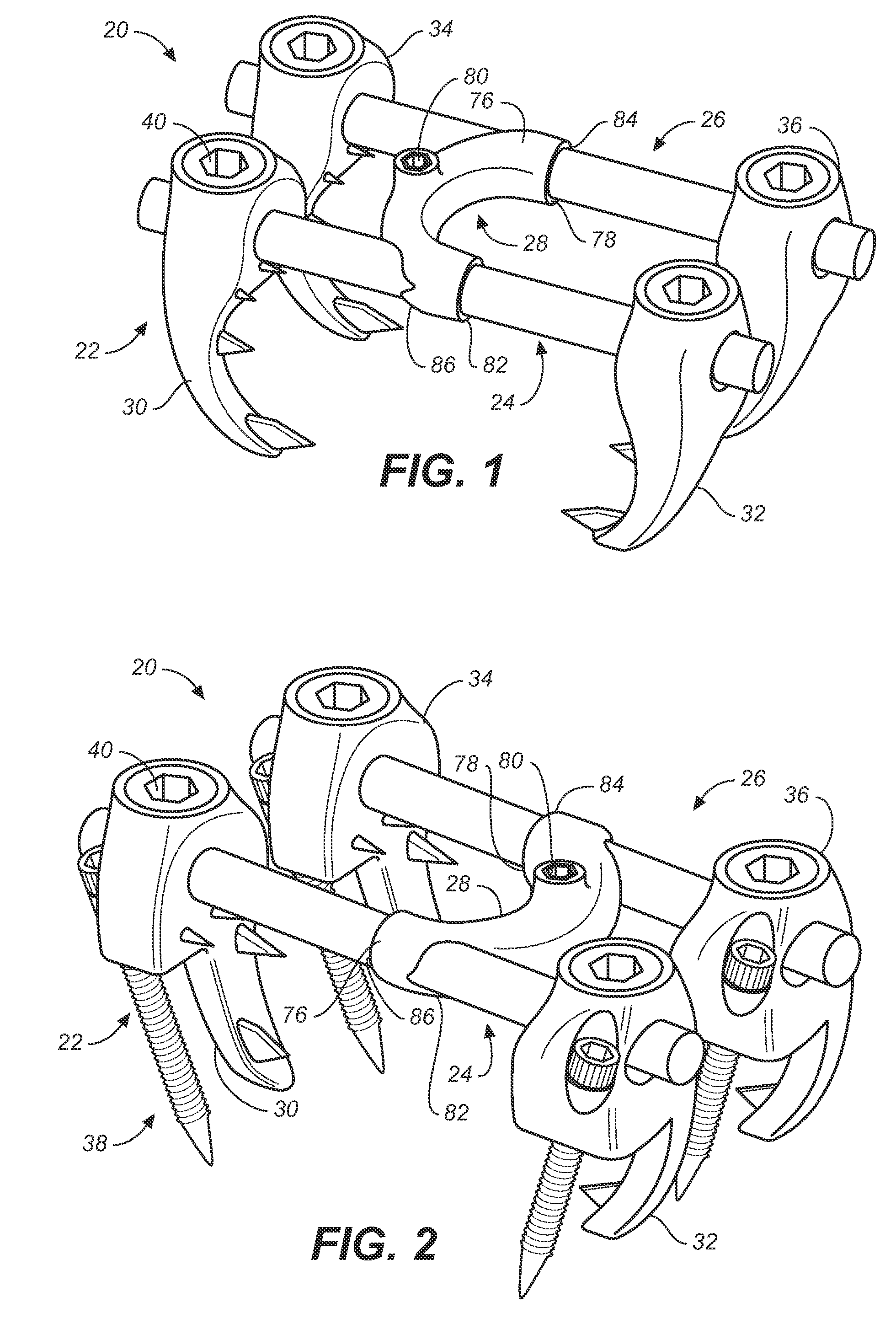
[0026] In one embodiment of the present invention, an implant is provided that can be placed between the lamina through a posterior, minimally invasive surgical technique and is designed to treat degenerative disorders of the spine. Degenerative disc disease results from the natural process of aging and ultimately affects all structures of the vertebral motion segment. The degenerative process causes loads that are normally borne by the intervertebral disc to be transferred to the articular facet joints, ligaments and other soft tissues of the spine.
[0027] The benefits of this implant are: The articular facets provide an excellent structure to which to attach an implant. They consist of very strong cortical bone, the strongest in the lumbar vertebra. There are no major nerves or vessels in the area approximate to the lateral aspect of facets, making them also a very safe point of attachment.
[0028] Attached to hooks, a crosslink can be positioned as far anterior as is possible with...
PUM
 Abstract
Description
Claims
Application Information