Implants with Transition Surfaces and Related Processes

a transition surface and implant technology, applied in the field of joint replacement surgery, can solve the problems of other types of problems, bone-on-bone contact can be very painful and damaging, and the bone beneath the cartilage is left exposed, so as to reduce pain, reduce blood loss, and accelerate recovery time

Inactive Publication Date: 2008-03-06
SMITH & NEPHEW INC
View PDF41 Cites 48 Cited by
  • Summary
  • Abstract
  • Description
  • Claims
  • Application Information

AI Technical Summary

Benefits of technology

[0012]In some cases, implants adapted to be installed on such resected femurs feature a transition surface which corresponds to the transition resection that has been controllably located and oriented relative to the femur as mentioned above. Such a transition when properly located aims to create a smooth transition from implant surface to bone surface by, among other things, reducing surface discontinuity such as implant and / or bone overhang. Preferably, the transition between bone and implant in such cases is located so that only anatomical lateral condyle surfaces articulate relative to the tibia in the knee joint in which the implant has been installed.

Problems solved by technology

When joint cartilage is worn away, the bone beneath the cartilage is left exposed, and bone-on-bone contact can be very painful and damaging.
Other types of problems can occur when the bone itself becomes diseased.
Such procedures often require sacrifice of the anterior and posterior cruciate ligaments.
However, many patients who develop knee arthritis experience issues isolated to the medial (inner) compartment and the patellofemoral (knee cap) part of the joint, while the lateral (outer) compartment of the joint remains healthy.
However, there is no known solution or method for marking the boundary for bicompartmental knee replacement.

Method used


Image

  • Implants with Transition Surfaces and Related Processes
  • Implants with Transition Surfaces and Related Processes
  • Implants with Transition Surfaces and Related Processes

Examples


Embodiment Construction

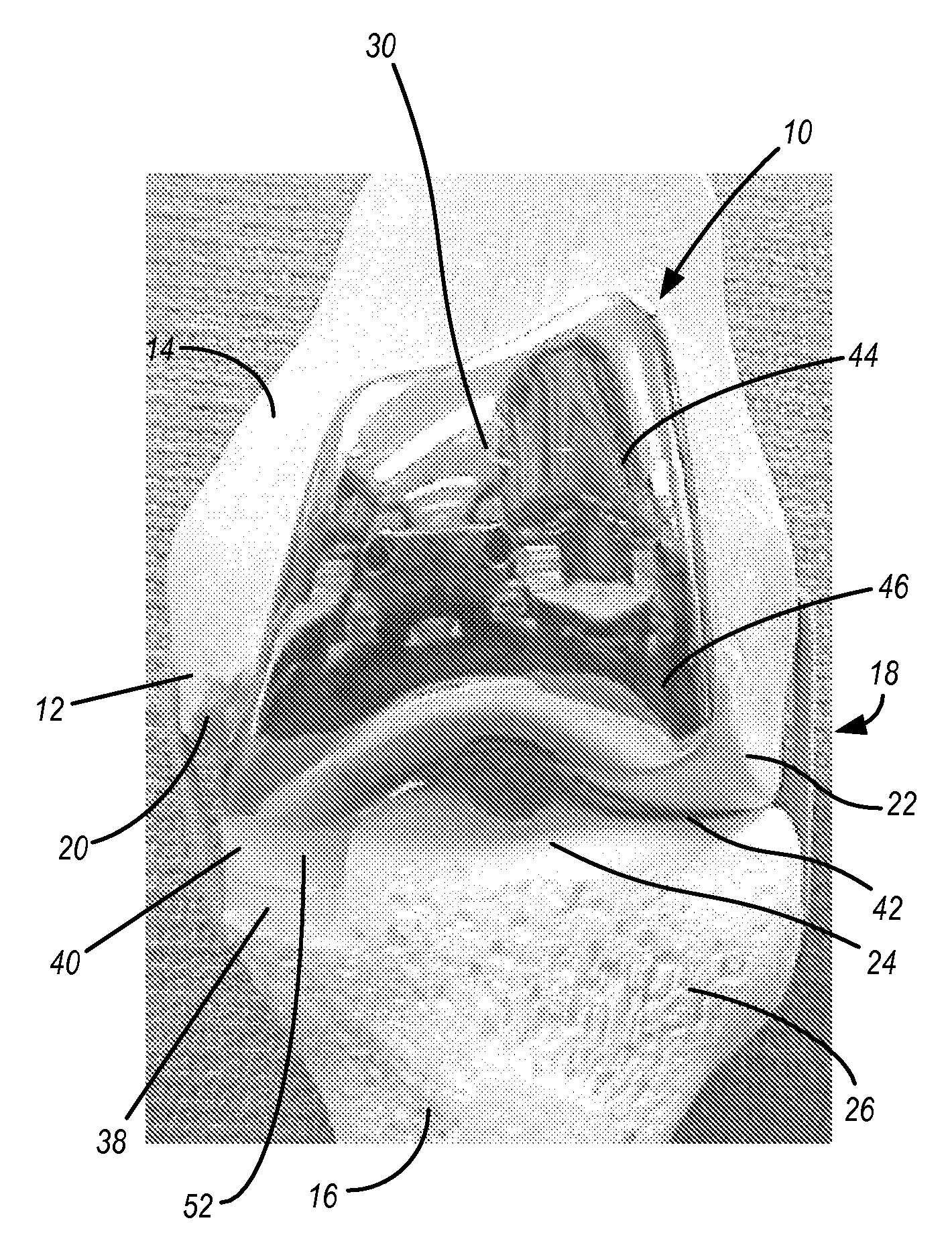
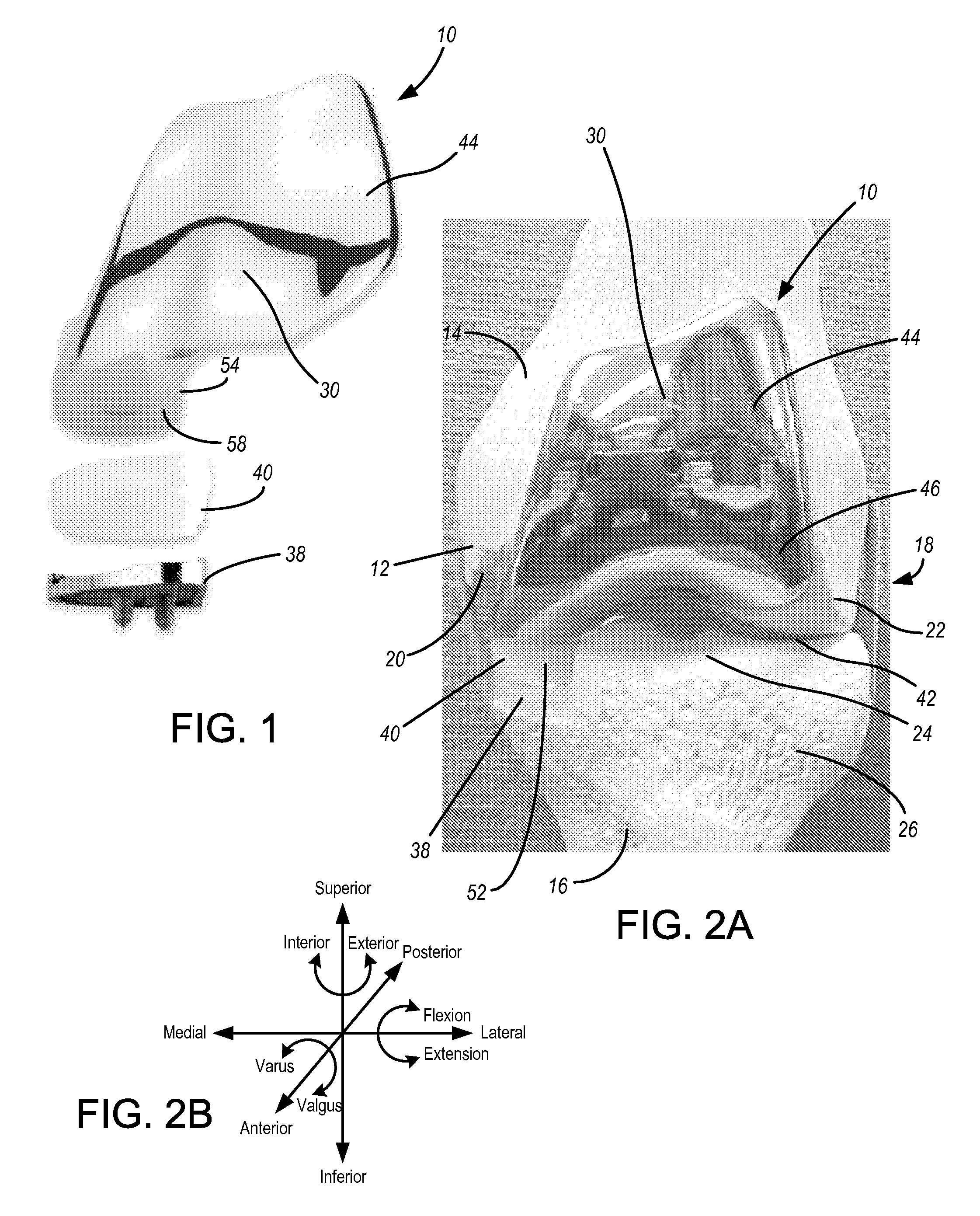
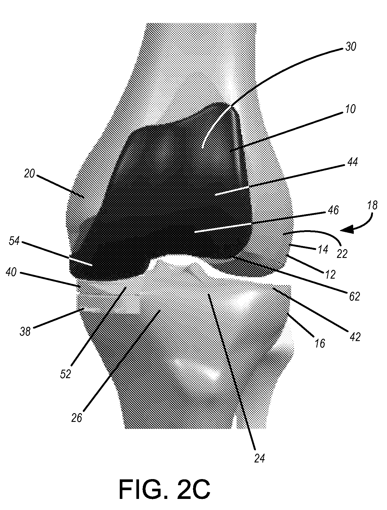
[0066]FIGS. 1 and 2A are front views of an implant 10 according to an embodiment of the invention. Implant 10 is adapted to be installed on the distal portion 12 of a human femur 14. The femur can be that of a human or other being with appropriate hinge joints. FIG. 2A shows an implant 10 placed on a sawbones model of a human femur 14. Anatomically, the femur 14 cooperates with the tibia 16 to form the knee joint 18. The distal portion 12 of the femur 14 includes two condyles, a medial condyle 20 and a lateral condyle 22. These condyles articulate (move in gross motion, whether rotational or translational or both) relative to the tibial plateau 24 which is a surface on the proximal portion 26 of tibia 16. Not shown is a patella which is connected to a patella tendon, also not shown, which in turn inserts on the tibia and attaches to the head of quadricep muscles to apply traction for extension of the knee joint. The patella tracks, as by sliding, in the patellofemoral channel 30. Pa...


PUM


Abstract

Implants, and processes for installing them, which replace the medial condyle and portions of the patellofemoral channel but preferably not portions of the lateral condyle that articulate relative to the tibia. Processes are provided which allow proper location and orientation of an anterior resection and a distal resection on the femur, which make use of a transition point which can be designated on the bone, for navigating proper positioning of such implants. Proper positioning of the implant relative to the femur for insuring a smooth transition between lateral portions of the implant and the lateral condyle is thus reduced to determining proper medial / lateral location of the implant on the anterior and distal resections. Such implants and processes can allow, among other things, for controlled location and orientation of an implant on the bone which saves lateral compartment bone, which eliminates the need to sacrifice the anterior and posterior cruciate ligaments, and which is adapted for minimally invasive surgery with its attendant benefits.

Description

[0001]This application claims the benefit of the following U.S. Provisional Applications Ser. No. 60 / 828158, filed Oct. 4, 2006, titled Instrumentation for Bicompartmental Knee; Ser. No. 60 / 824696, filed Sep. 6, 2006, titled Instrumentation for Bicompartmental Knee; and Ser. No. 60 / 825533 filed Sep. 13, 2006, titled Variable Transition Referencing Guide, the entire contents of each of which are hereby incorporated by reference.FIELD OF THE INVENTION[0002]The invention relates to implants and processes for use in joint surgery, particularly knee replacement surgery. In certain embodiments, methods are provided for locating and using a transition point on the femur for proper positioning of resections that are intended to receive a femoral component during a surgical procedure. Implants are provided according to certain embodiments that replace the medial condyle and part of the patellofemoral channel of the femur, but preferably do not replace portions of the lateral condyle that art...

Claims


Application Information

Patent Timeline
Patent Type & Authority Applications(United States)
IPC IPC(8): A61F2/38A61B17/90
CPCA61B17/155A61B17/1764A61F2002/3895A61F2/3877A61F2/3859A61F2/38A61F2002/30001
Inventor DEES, ROGER RYANJORDAN, JASON
Owner SMITH & NEPHEW INC
Why Eureka
Try Eureka