Vehicle control system

a technology of vehicle control and control system, applied in the direction of process and machine control, using reradiation, instruments, etc., can solve the problems that the vehicle speed control cannot be executed in accordance with actual road conditions, and the vehicle speed control cannot be executed

Active Publication Date: 2008-03-06
DENSO CORP
View PDF22 Cites 90 Cited by
  • Summary
  • Abstract
  • Description
  • Claims
  • Application Information

AI Technical Summary

Benefits of technology

[0007]The present invention also has a secondary object to provide a vehicle control system capable of reflecting the feel of danger that a driver will have when entering a curving road.

Problems solved by technology

Therefore, the reference lateral acceleration rate must be set adequately, and vehicle speed control cannot be executed in accordance with actual road conditions and the state of the vehicle unless the reference lateral acceleration rate is adequately set.
It cannot execute vehicle speed control taking the feel of danger that drivers will have on a curving road into account.

Method used


Image

  • Vehicle control system
  • Vehicle control system
  • Vehicle control system

Examples


first embodiment

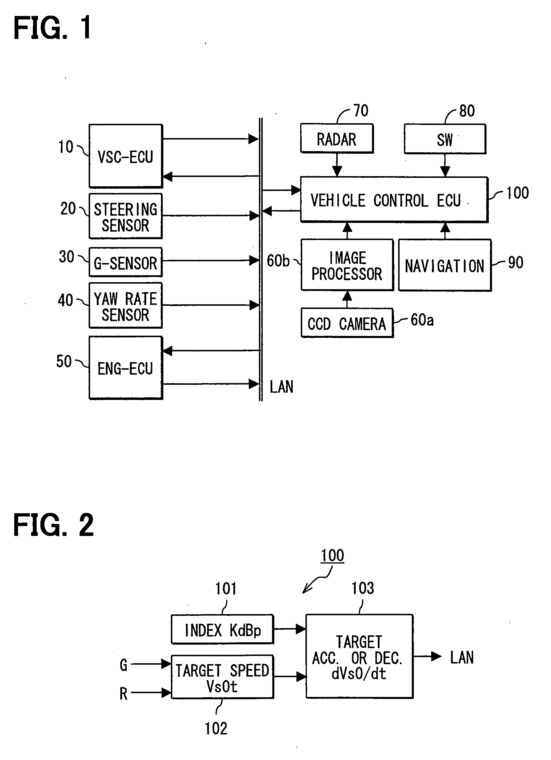
[0028]As shown in FIG. 1, a driving support system includes a VSC-ECU 10, a steering angle sensor 20, a G-sensor 30, a yaw rate sensor 40, an ENG-ECU 50, a CCD camera 60a, an image recognition processor 60b, a radar 70, operation switches 80, a navigation device 90, and a vehicle control ECU 100. This system is mounted on a vehicle (controlled vehicle), which is to be controlled.

[0029]The VSC-ECU 10 controls a brake actuator (not shown) which applies a braking force to the controlled vehicle, and it has a VSC (vehicle stability control which is a registered trademark) function for suppressing a side slip of the controlled vehicle. The VSC-ECU 10 receives information on a target deceleration rate through an in-vehicle LAN and controls a brake actuator such that the target deceleration is attained in the controlled vehicle. The VSC-ECU 10 also transmits information on the speed (vehicle speed) Vs0 and the brake pressure of the controlled vehicle to the in-vehicle LAN.

[0030]The steerin...

second embodiment

[0070]The second embodiment is different from the first embodiment in that the driving support system executes deceleration control to avoid a collision between a controlled vehicle and an obstacle present on a road in front of the vehicle in the traveling direction thereof or to decelerate the controlled vehicle in passing the obstacle.

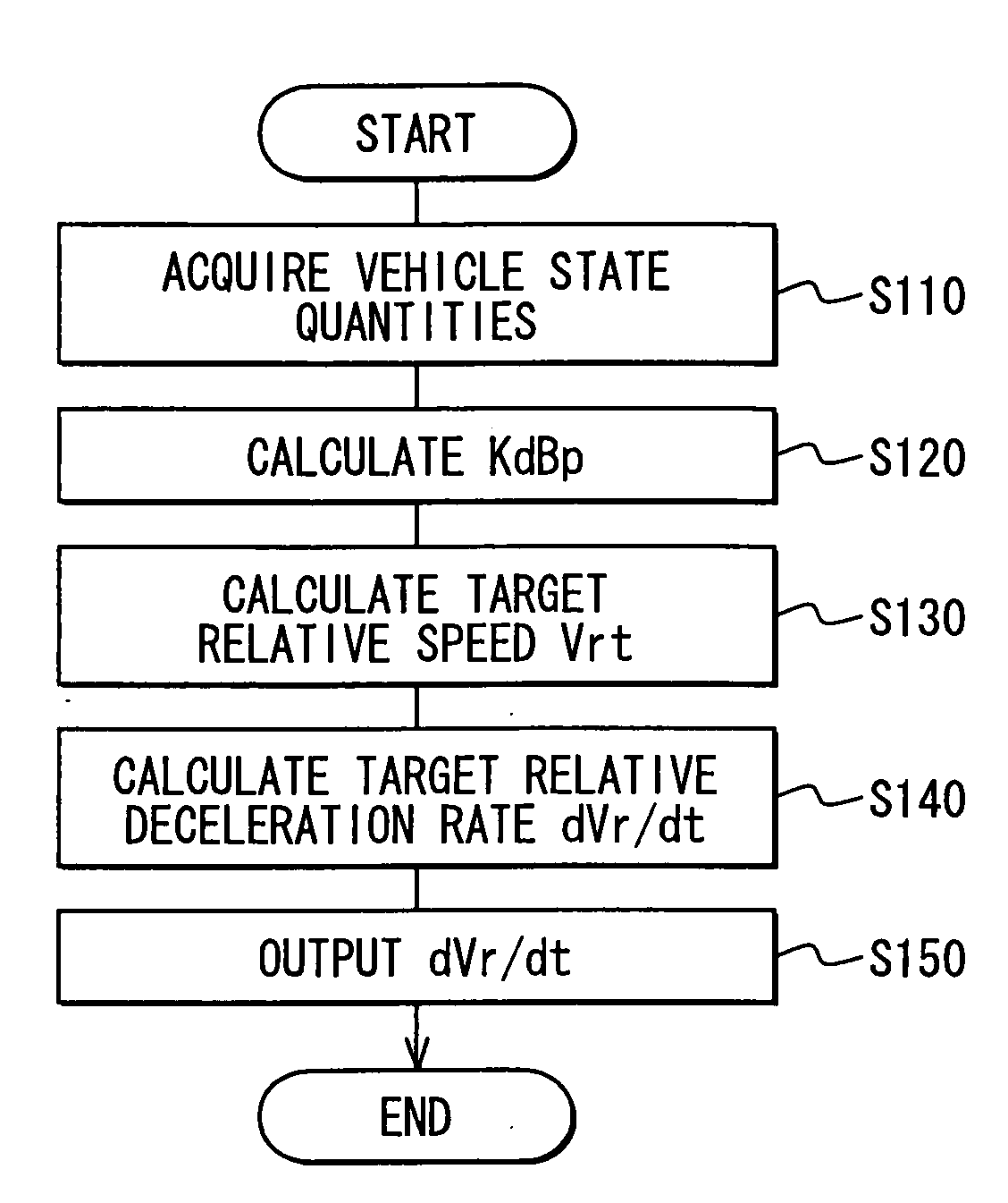
[0071]As shown in FIG. 5, the vehicle control ECU 100 includes, in addition to the evaluation index calculation unit 101, a turning radius calculation unit 112, a target relative speed calculation unit 113 and a target relative deceleration calculation unit 114. The evaluation index calculation unit 101 calculates the present value KdBp of the evaluation index. The turning radius calculation unit 112 calculates a turning radius Ro of the controlled vehicle required for the controlled vehicle to avoid a collision with an obstacle (or to pass the obstacle). The target relative speed calculation unit 113 calculates a target relative speed Vrt between th...

third embodiment

[0095]The third embodiment is similar to the first and second embodiments in that, operations similar to those of the driving support system of the first embodiment are executed when there is no obstacle on a curving road, and deceleration control is executed to avoid a collision with an obstacle when there is the obstacle on the curving road.

[0096]As shown in FIG. 8, the vehicle control ECU 100 according to the third embodiment is different in that an output determination unit 120 is provided.

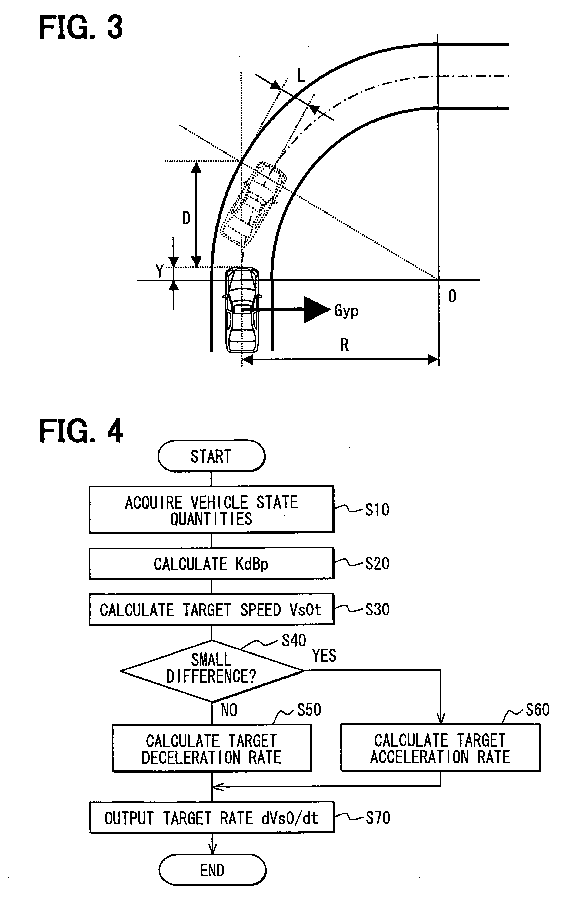
[0097]When an obstacle such as a leading vehicle exists on a curving road in front of the controlled vehicle in an overlapping relationship with a future locus of a projected surface of the controlled vehicle, the evaluation index calculation unit 101 calculates the present value KdBp of the index for evaluating a state of decrease or increase in the distance between the obstacle and the controlled vehicle using the expression (16) from a distance D between the controlled vehicle and the obsta...


PUM


Abstract

A vehicle control system controls the speed of a vehicle according to actual road conditions and state of the vehicle. The control system acquires a present value of lateral acceleration occurring in a direction lateral to a controlled vehicle when the controlled vehicle avoids a collision with an obstacle or passes the obstacle. A target relative speed between the obstacle and the controlled vehicle is calculated from the present value of lateral acceleration and a turning radius of the controlled vehicle required for the controlled vehicle to avoid a collision with the obstacle or to pass the obstacle. Then, deceleration control is executed based on target relative deceleration rate at which the controlled vehicle is to be decelerated to reach the target relative speed.

Description

CROSS REFERENCE TO RELATED APPLICATION[0001]This application is based on and incorporates herein by reference Japanese Patent Applications No. 2006-239420 filed on Sep. 4, 2006 and No. 2007-128567 filed on May 14, 2007.FIELD OF THE INVENTION[0002]The present invention relates to a vehicle control system.BACKGROUND OF THE INVENTION[0003]Various vehicle control systems for controlling the speed of a vehicle are proposed (for example, U.S. Pat. No. 5,928,299 which corresponds to JP 3432881). A vehicle control system disclosed in U.S. Pat. No. 5,928,299 identifies the distance (estimated distance) required for a controlled vehicle to stop within a predetermined time when it is decelerated from a vehicle speed at predetermined deceleration rate. Then, the control system sets a reference node in a preliminary controlled vehicle position located ahead the position of the controlled vehicle by the estimated distance and also sets another reference node in a position located ahead the refere...

Claims


Application Information

Patent Timeline
Patent Type & Authority Applications(United States)
IPC IPC(8): B60K31/00B60W40/06B60W40/10
CPCB60W40/072B60W2720/125B60W40/105B60W40/109B60W2420/52B60W10/20B60W30/09B60W30/12B60W30/143B60W30/18145B60W2520/10B60W2520/125B60W2550/146B60W2720/106B60W40/076B60W2552/30B60W2555/20
Inventor ISAJI, KAZUYOSHITSURU, NAOHIKO
Owner DENSO CORP
Why Eureka
Try Eureka