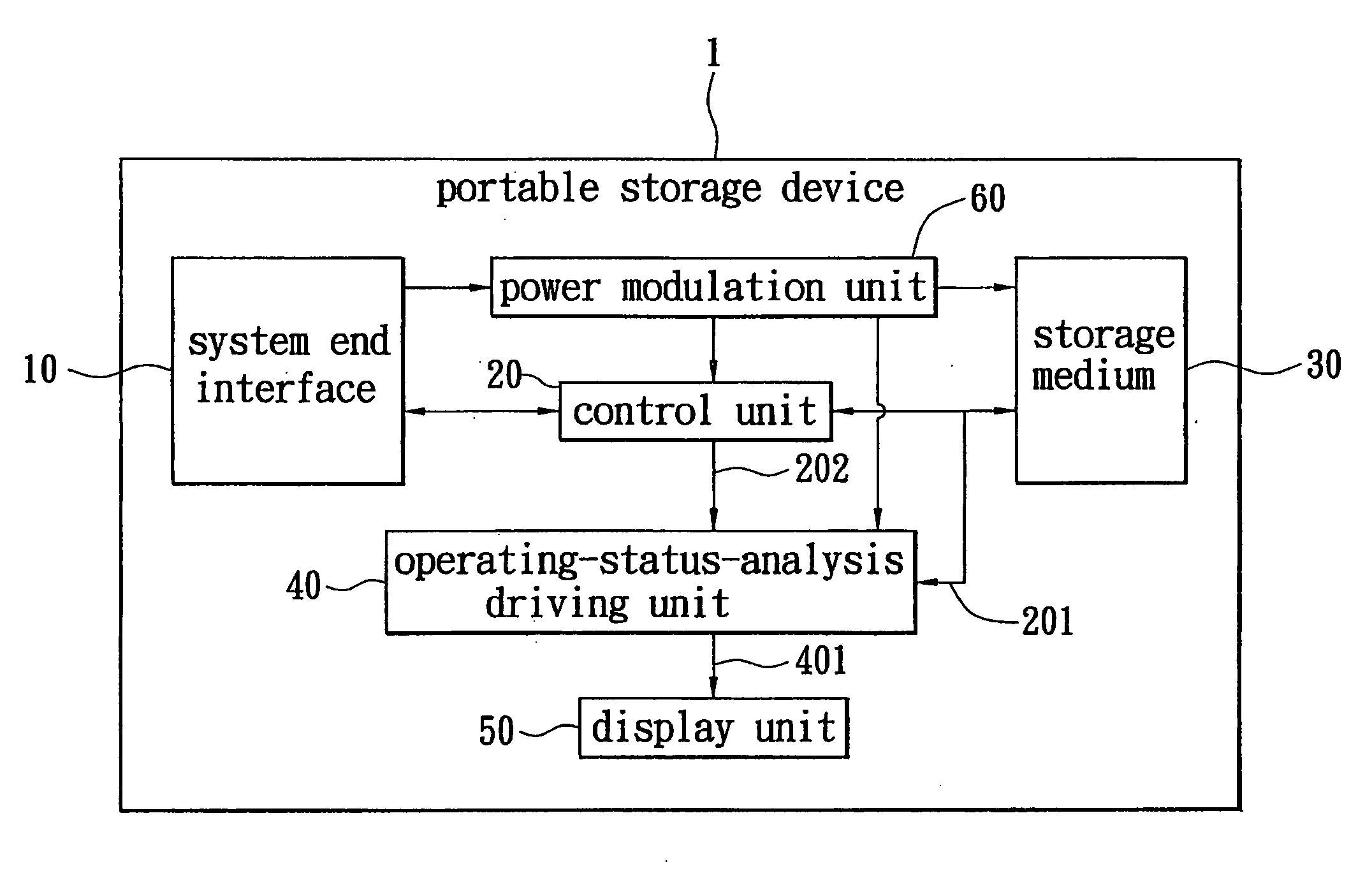
Portable storage device with operating status display
a storage device and operating status technology, applied in the field of portable storage devices, can solve the problems of failure of conventional storage devices, inability to immediately indicate real-time information about operating status or access speed, etc., and achieve the effect of saving information
- Summary
- Abstract
- Description
- Claims
- Application Information
AI Technical Summary
Benefits of technology
Problems solved by technology
Method used
Image
Examples
first embodiment
[0030]FIG. 3 illustrates the portable storage device 1 according to the present invention. The portable storage device 1 is the flash drive 1′. The display unit 50 is arranged by five LEDs L1˜L5 in line. All the LEDs L1˜L5 will light or not, change the illumination or color thereof in correspondence with the operating status of the flash drive 1′. And the combination of changes and locations of the LEDs L1˜L5 will tell the exact operating status of the flash drive 1′. For example, if the flash drive 1′ is at the standby state, the LEDs L1˜L5 can be all illuminated or all extinguish. For further entertaining effect, the LEDs L1˜L5 can change the illumination at the same speed slowly. If the flash drive 1′ is at the read state, most LEDs can light with the same period, such as the first LED L1, the second LED L2 and the third LED L3, but with various illuminations, a moving spot formed by the three LEDs can indicate the transmission speed of information. The faster the moving spot act...
second embodiment
[0034]FIG. 4 illustrates the portable storage device 1 according to the present invention. The portable storage device 1 also is the flash drive 1′. The display unit 50 is a LCD 50′, which includes an operating-status display area 51 for demonstrating the state of the portable storage device 1. When the flash drive 1′ is at the standby state, the operating-status display area can be clear and blank.
[0035]Referring to FIG. 4A, the flash drive 1′ is at the read state. The moving indication on the operating-status display area 51 is from the flash drive 1′ to the processor-based system, so that the repeat indication specifies the read state of the flash drive 1′. At the same time, the repeat speed of the moving indication also shows the real transmission speed.
[0036]Referring to FIG. 4B, the flash drive 1′ is at the record state. Differing from FIG. 4A, the illumination order of the LEDs L1˜L5 is from the processor-based system to the flash drive 1′.
fourth embodiment
[0037]FIG. 5 and 6 illustrates the portable storage device 1 according to a third and fourth embodiment of the present invention respectively. The portable storage device 1 can be adapted for a card reader 1″ and a memory card 30′. Illustrated in FIG. 5, the card reader 1″ includes a plurality of LEDs surrounding thereof. The LEDs form the normal and inverse circle directions in read or record state. Illustrated in FIG. 6, the card reader 1″ includes the LCD 50′, which also can indicate the operating status while the memory card 30′ applies.
[0038]The LCD 50′ can show not only the gradual dragging moving indication, but also other patterns or characters which are able to reveal the operating status.
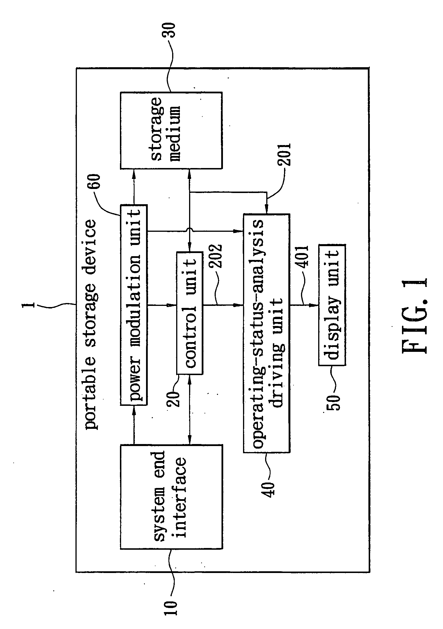
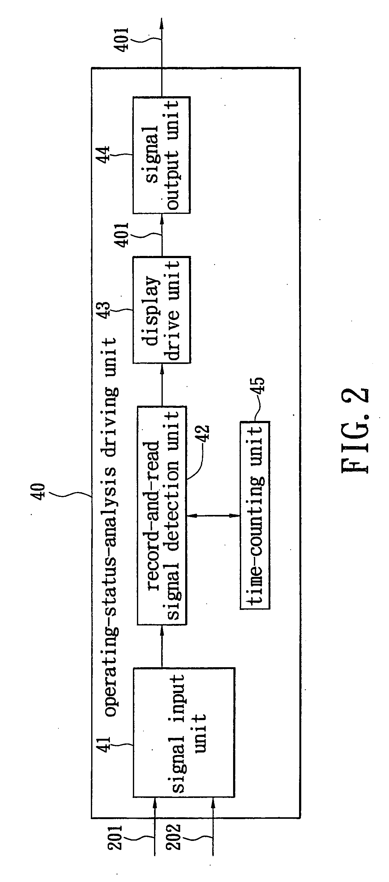
[0039]Concluding the description mentioned above, the portable storage device 1 can detect the read / record state automatically and further modify the demonstration of the display unit in real time. No more cost will raise the additional values of the portable storage device, and motive dem...
PUM
 Abstract
Description
Claims
Application Information
 - R&D
- Intellectual Property
- Life Sciences
- Materials
- Tech Scout
- Unparalleled Data Quality
- Higher Quality Content
- 60% Fewer Hallucinations
Browse by: Latest US Patents, China's latest patents, Technical Efficacy Thesaurus, Application Domain, Technology Topic, Popular Technical Reports.
© 2025 PatSnap. All rights reserved.Legal|Privacy policy|Modern Slavery Act Transparency Statement|Sitemap|About US| Contact US: help@patsnap.com


