Stealth Laser Sighting System For Firearms

a laser sighting and laser sighting technology, applied in the field of firearms laser sighting systems, can solve the problems of personal injury or even death, inability to accurately sight long-range targets, and inability to quickly respond to large-scale changes, etc., to achieve accurate sighting of long-range targets.

Inactive Publication Date: 2008-03-13
PINE JERROLD SCOTT +1
View PDF10 Cites 151 Cited by
  • Summary
  • Abstract
  • Description
  • Claims
  • Application Information

AI Technical Summary

Benefits of technology

[0015]It is further an aspect of the present invention to provide image zoom capabilities to accurately sight long-range targets.

Problems solved by technology

For a firearm to be used in this manner it needs to be quickly and accurately discharged or else it may provoke return fire and result in personal injury or even death.
This is not a process that lends itself to rapid response in an emergency situation.
The accuracy when firing in this manner is marginally effective at short distances and relatively ineffective at longer distances.
The ability to aim in low light situations with a visible flashlight introduces another dangerous issue.
Night vision equipment has in the past been bulky and is certainly not designed for rapid response.
Not only is the time required for this sequence potentially hazardous, the additional motions required can also disclose your location and intent.

Method used


Image

  • Stealth Laser Sighting System For Firearms
  • Stealth Laser Sighting System For Firearms
  • Stealth Laser Sighting System For Firearms

Examples


Embodiment Construction

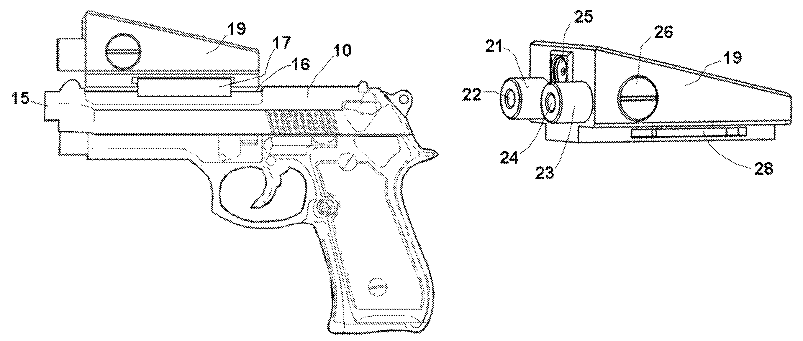
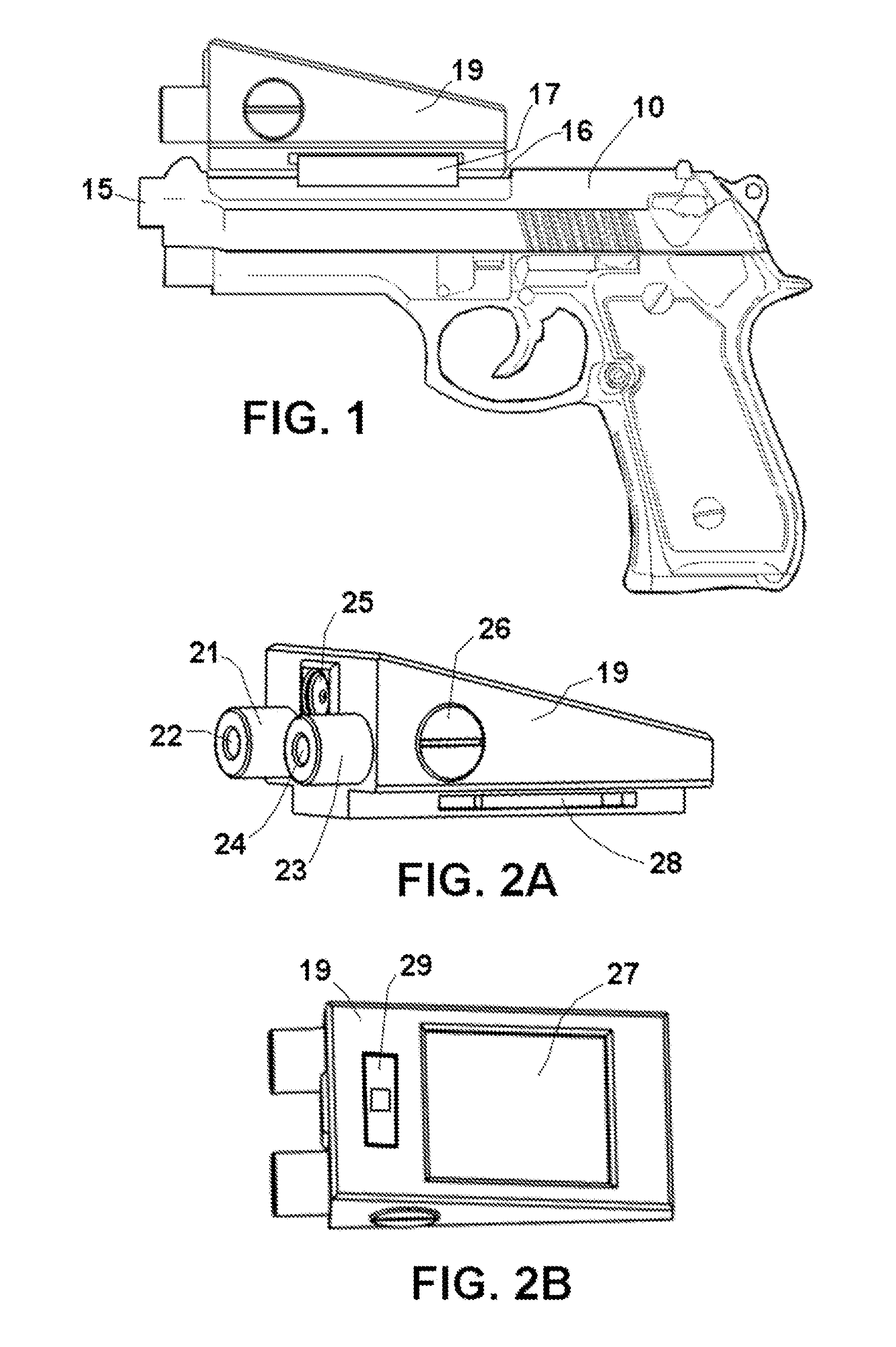
[0033]Referring to FIG. 1 there is shown a typical handgun 10 that as illustrated is by way of example a Beretta pistol. The handgun 10 has a barrel 15 that is the tube that a bullet travels down when fired. Along the top of the barrel 15 is a mounting base 16, which fastens accessories such as gun sights and scopes to the firearm. There are several types of mounting bases: a Weaver base, a Ruger base, a Leopold base, various .22 bases or “dovetail” bases are the most common. Attached to the mounting base 16 is mounting adapter 17 which fastens a stealth laser sighting system 19 in accessory form in accordance with the present invention to the handgun 10 and contains mechanical adjustment for elevation and windage.

[0034]FIG. 2A illustrates the stealth laser sighting system 19, shown by way of example in accessory form in accordance with the present invention. The stealth laser sighting system 19 houses all the components necessary to project a non-visible or visible laser dot, and t...


PUM


Abstract

A stealth laser sighting system for a firearm includes a non-visible laser and night imaging device with display. The stealth laser sighting system combines all of the features required for stealth laser sighting within a self-contained accessory. The stealth laser sighting system provides for an optional visible laser system. and can include features such as electronic calibration, laser rangefinder compensation, target zoom, projected graphic laser marking, and windage and elevation adjustments on a graphical overlay. The stealth laser sighting system can be packaged as an accessory or all of the features can be integrated into a firearm.

Description

BACKGROUND OF THE INVENTION[0001]Many people own small firearms, such as revolvers, pistols, and rifles for sport and for protection. The United States Constitution and state laws permit people to protect themselves. A person may use force, even deadly force, against another person when he / she reasonably believes that such force is immediately necessary for the purpose of protecting him / herself against the use of unlawful force by such other person. For a firearm to be used in this manner it needs to be quickly and accurately discharged or else it may provoke return fire and result in personal injury or even death.[0002]A very simplified process describing the discharge of a firearm, such as a handgun, is to load with ammunition, aim the gun at a target, and fire the gun by actuating a trigger. The most common means to aim a gun is the visual alignment of a target with front and rear mechanical sights typically located along the top barrel of the gun. While aiming, the top of the fr...

Claims


Application Information

Patent Timeline
Patent Type & Authority Applications(United States)
IPC IPC(8): F41G1/00
CPCF41G1/35
Inventor PINE, JERROLD SCOTTMICHAELS, PAUL M
Owner PINE JERROLD SCOTT
Why Eureka
Try Eureka