Compact Ringlight

Inactive Publication Date: 2008-03-13
SYSTATION SEMICON +1
View PDF7 Cites 20 Cited by
  • Summary
  • Abstract
  • Description
  • Claims
  • Application Information

AI Technical Summary

Benefits of technology

[0014]To attain this, the present invention generally comprises a substantially conical or cylindrically shaped reflective inner surface and a ringlight positioned such that light from the ringlight is directed across and above the inspection area but not incident upon the inspection area until it passes across the optical axis and reflects off of the opposing reflective surface, which then directs it toward the inspection area. The light thus travels a longer distance than a conventional ringlight and thus more nearly collimates the light rays. A baffle is used to block light from illuminating the inspection area prior to reflecting off the opposing reflective surface. Alternatively a lens could be used in place of a baffle. Also, a light source with a well directed or narrow output could be used. Other means are possible to inhibit light from illuminating the inspection area prior to reflecting off of the reflecting surface. Additionally, the substantially conical or cylindrically shaped reflective surface could be octagonal or polygonal and have nea

Problems solved by technology

Therefore ring locations do not accurately correspond to actual ball locations.
While these devices of prior art may be suitable for the particular purpose to which they address, they are not as suitable to maxim

Method used


Image

  • Compact Ringlight
  • Compact Ringlight
  • Compact Ringlight

Examples


Example

[0025]Turning now descriptively to the drawings, in which similar reference characters denote similar elements throughout the several views, the attached figures illustrate the compact ringlight.

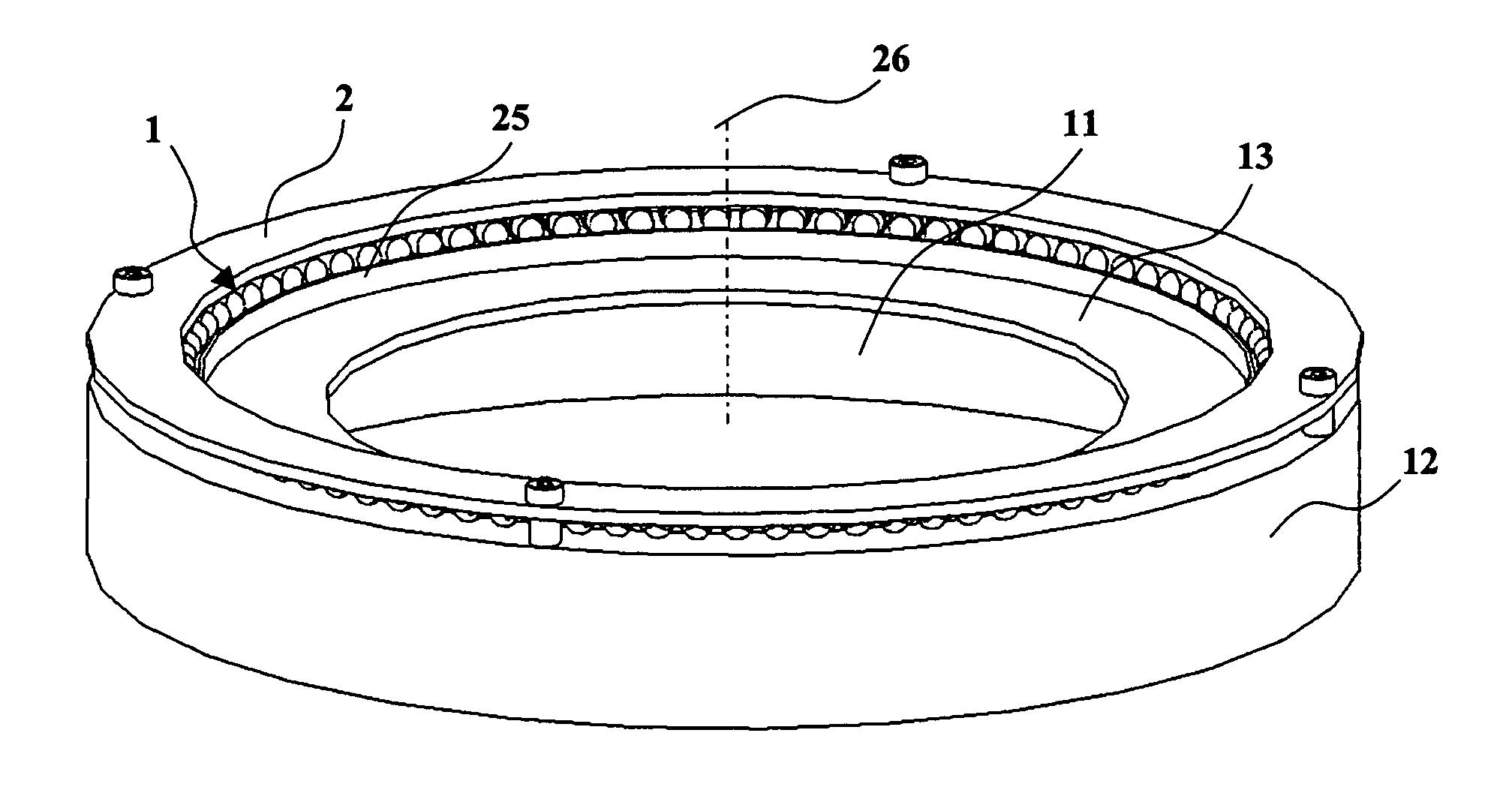
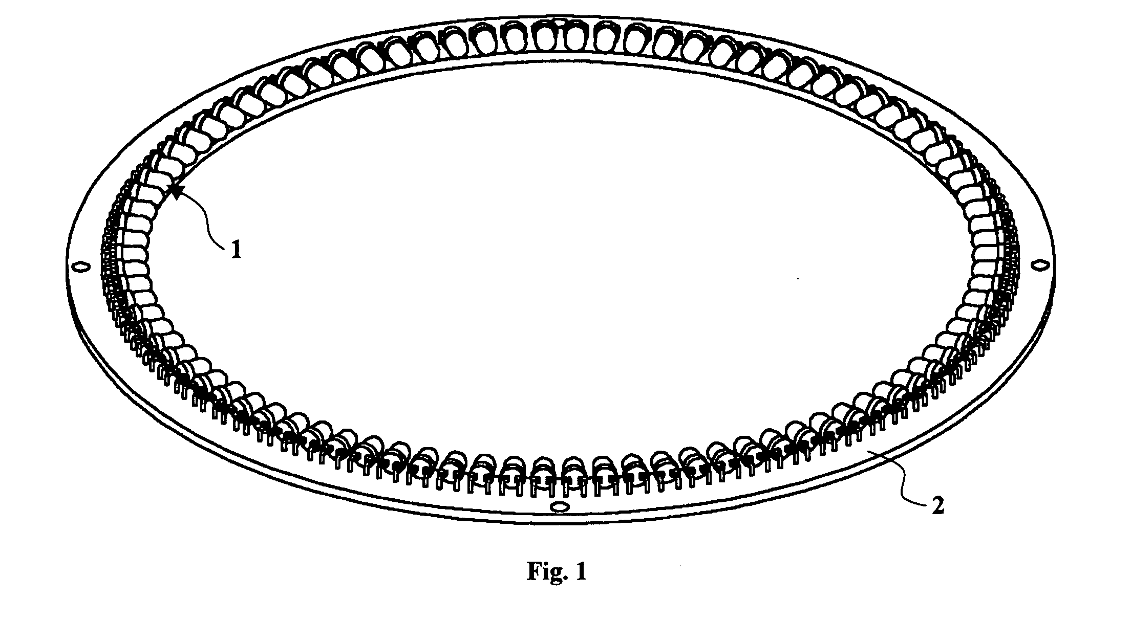
[0026]FIG. 4 illustrates a preferred embodiment of the invention. A circular array of LEDs 1 is attached to a circuit board 2. The LEDs are positioned to emit light inward toward the ringlight's axis of symmetry 26 which is also the optical axis of the system. A conical reflective surface 11 is formed by the inner surface of a piece of metal 12. A ring 13 forms an aperture so that light from the LEDs cannot directly illuminate the inspection area but must cross above the inspection area (passing thru the optical axis of the system) and be reflected off of the reflective surface on the opposite side before illuminating the inspection area. A light shaping diffuser 25 (FIG. 5) radially diffuses light.

[0027]FIG. 6 is a cut-away side view of the invention positioned above BGA device 30. LED 14 p...


PUM


Abstract

A compact ringlight that emulates the performance of a much larger ringlight is disclosed. The invention utilizes a ringlight source and a conical or cylindrical reflector such that light first crosses the optical axis and then is reflected back towards the inspection area. This light is particularly useful for inspecting electronic semiconductor devices.

Description

CROSS REFERENCE TO RELATED APPLICATIONS[0001]This application claims the benefit of provisional patent application Ser. No. 60 / 842,769 filed Sep. 7, 2006 by the present inventor.FEDERALLY SPONSORED RESEARCH[0002]Not Applicable.SEQUENCE LISTING OR PROGRAM [0003]Not Applicable.BACKGROUND[0004]1. Field of the Invention[0005]The present invention relates generally to light sources and more specifically it relates to ringlights commonly used for machine vision inspection of electronic semiconductor devices.[0006]2. Prior Art[0007]It can be appreciated that ringlights have been in use for years. Ringlights are commonly used in machine vision applications where it is often desired to have a light source, emanating from a circle, surround the inspection area. Ringlights are often used as darkfield illuminators to illuminate vertical features such as scratches, chip-outs, debris, pin 1 dimples and laser markings in semiconductor packages. They are also often used to inspect BGA (Ball Grid Ar...

Claims


Application Information

Patent Timeline
IPC IPC(8): G01N21/47F21V7/00
CPCG01N21/8806F21K9/00F21K9/68F21Y2103/33
Inventor SHIRES, MARK RICHARDSTERN, HOWARD
Owner SYSTATION SEMICON
Why Eureka
Try Eureka