Position measuring arrangement

a technology for positioning measurement and arrangement, applied in measurement devices, instruments, material analysis through optical means, etc., can solve the problems of increasing the complexity, and therefore the cost, of correspondingly constructed position measurement arrangement, and the increase of the outlay, or the cost, of such system

Active Publication Date: 2008-03-13
DR JOHANNES HEIDENHAIN GMBH
View PDF5 Cites 44 Cited by
  • Summary
  • Abstract
  • Description
  • Claims
  • Application Information

AI Technical Summary

Benefits of technology

[0008]It is an object of the present invention to provide an optical position measuring arrangement which makes possible the generation of phase-shifted scanning signals without the employment of optical polarization components. Moreover, the position measuring arrangement should be as tolerant as possible to possible fluctuation to error in the scanning distance.

Problems solved by technology

However, such optical polarization elements basically increase the complexity, and therefore also the cost, of correspondingly constructed position measuring arrangements.
This again results in a considerable increase in the outlay, or the costs, of such systems.
However, this is not the case in actuality, since it is necessary to provide an offset of the light beams between the first reflection and the second reflection, and different diffraction conditions exist at the two reflection locations.

Method used


Image

  • Position measuring arrangement
  • Position measuring arrangement
  • Position measuring arrangement

Examples


first embodiment

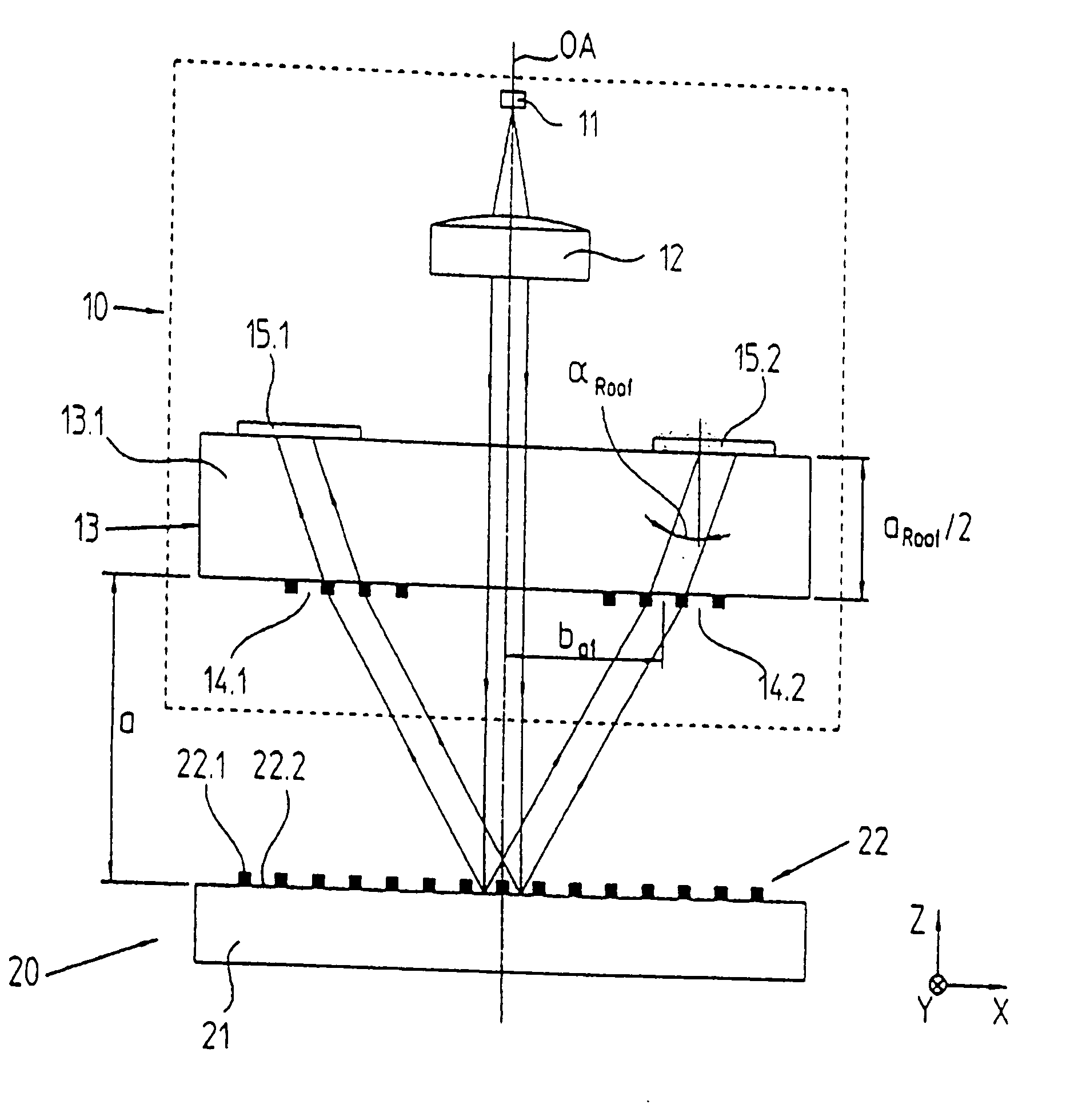
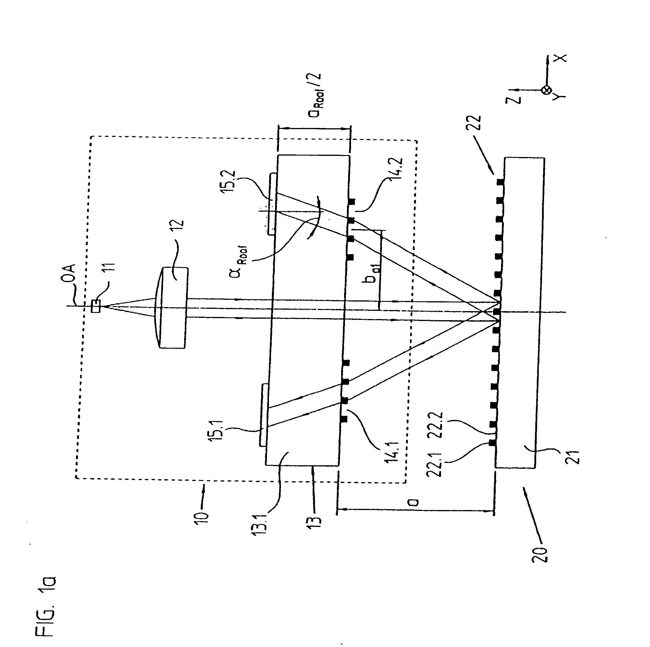
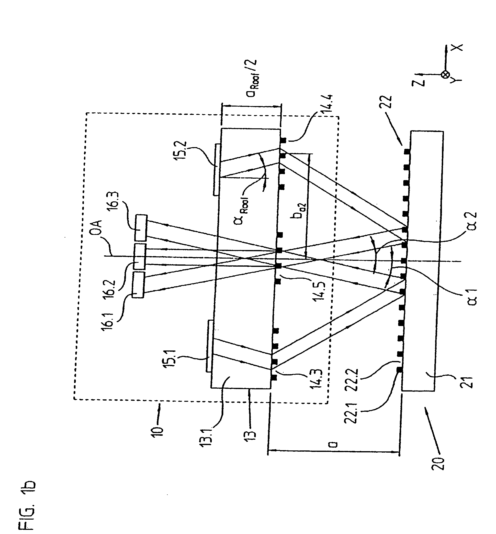
[0095]A first embodiment of the position measuring arrangement in accordance with the invention will be explained in what follows by FIGS. 1a to 1d. Here, FIGS. 1a and 1b respectively show in a schematized form partial scanning beam paths in a lateral view in the x-z plane. The scanning beam path from the light source 11 until the partial light beams impinge on the reflector elements 15.1, 15.2, is represented in FIG. 1a. FIG. 1b shows the scanning beam path following the partial light beams impinging on the reflector elements 15.1, 15.2 as far as the detector elements 16.1, 16.2, 16.3. FIGS. 1c and 1d respectively show views from above on the top and underside of the scanning plate 13 with the optical elements arranged there.

[0096]In this example, the position measuring arrangement in accordance with the present invention includes a reflection scale graduation 20, as well as a scanning unit 10, which can be moved in relation to it in at least one measuring direction x. The objects,...

second embodiment

[0131]A second embodiment of the position measuring arrangement in accordance with the present invention will be explained in what follows by FIGS. 3a to 3d. In principle, these drawing figures again show the same views of the position measuring arrangement as in the above example in FIGS. 1a to 1d.

[0132]In this example it has again been assured by the realized scanning beam path, or the arrangement of the various optical elements, in particular in the scanning unit 110, that a pair of light beams impinges in a non-parallel manner on the combining grating 114.5 in front of the detector elements, and several pairs of co-linear and interfering partial light beams are propagated downstream of the combining grating 114.5 in the direction of the detector elements 116.1 to 116.3.

[0133]The essential differences in regard to the first exemplary embodiment in FIGS. 1a to 1d will be explained in what follows. Thus, supplementing the first example it has been provided to arrange a splitting g...

third embodiment

[0162]A third embodiment of the position measuring arrangement in accordance with the present invention is represented in FIGS. 6a to 6d. Again, the representation corresponds to those of the previously explained in FIGS. 1a to 1d, 3a to 3d and 4a to 4d. Essentially only the definitive differences from these examples will be considered.

[0163]Thus, it has now been provided that the light beam, which is parallel after passing through the optical collimation device 412, impinges on a splitting grating 414.6 on the top of the scanning plate 413 and is split there into two partial light beams. Subsequently, both partial light beams reach an auxiliary splitting grating 414.7 on the underside of the scanning plate 413. By this auxiliary splitting grating 414.7 it is assured that the two split partial light beams impinge at the same impact location on the reflection scale representation 420. As can be seen in the view of FIG. 6d, the auxiliary splitting grating 414.7 can also include two se...


PUM


Abstract

A position measuring arrangement for detecting a relative position. The position measuring arrangement includes a reflection scale graduation and a scanning unit having a plurality of optical elements. The plurality of optical elements include a combining grating, a retro-reflector element, a scanning grating and detector elements. The optical elements are arranged so that:
    • 1) light beams and/or partial light beams of a scanning beam path act on the reflection scale graduation at least twice,
    • 2) a directional reversal of the incident partial light beams impinging on the reflection scale graduation perpendicularly with respect to the measuring direction takes place by the retro-reflector element; and
    • 3) a pair of partial light beams impinges in a non-parallel manner on the combining grating, and the combining grating brings the partial light beams impinging on the combining grating to interference, so that phase-shifted signals are detected by the plurality of detector elements.

Description

[0001]Applicants claim, under 35 U.S.C. § 119, the benefit of priority of the filing date of Sep. 12, 2006 of a German patent application, copy attached, Serial Number 10 2006 042 743.2, filed on the aforementioned date, the entire contents of which is incorporated herein by reference.BACKGROUND OF TIE INVENTION[0002]1. Field of the Invention[0003]The present invention relates to a position measuring arrangement for detecting the relative position of a scanning unit, as well as to a reflection scale graduation, which can be moved in relation to the latter in at least one measuring direction, wherein the scanning unit includes a plurality of optical elements.[0004]2. Discussion of Related Art[0005]A high-resolution optical position-measuring arrangement is known from WO 02 / 23131 A1 and U.S. Pat. No. 7,019,842, the entire contents of which are incorporated herein by reference. Besides a reflection scale graduation embodied, for example, as a linear incident light scale, it includes a ...

Claims


Application Information

Patent Timeline
Patent Type & Authority Applications(United States)
IPC IPC(8): G01B11/02G01D5/36
CPCG01D5/38
Inventor SANDIG, KARSTENHOLZAPFEL, WOLFGANG
Owner DR JOHANNES HEIDENHAIN GMBH
Why Eureka
Try Eureka