
Method and system for guiding a vehicle with vision-based adjustment

a technology of vision adjustment and vehicle, applied in the direction of process and machine control, distance measurement, instruments, etc., can solve the problems of unreliable gps-only navigation system in certain locations or environments, and the position error of more than 50 centimeter (20 inches) is typical for five percent of the operation tim

Active Publication Date: 2008-03-13
DEERE & CO
View PDF18 Cites 28 Cited by
  • Summary
  • Abstract
  • Description
  • Claims
  • Application Information

AI Technical Summary

Benefits of technology

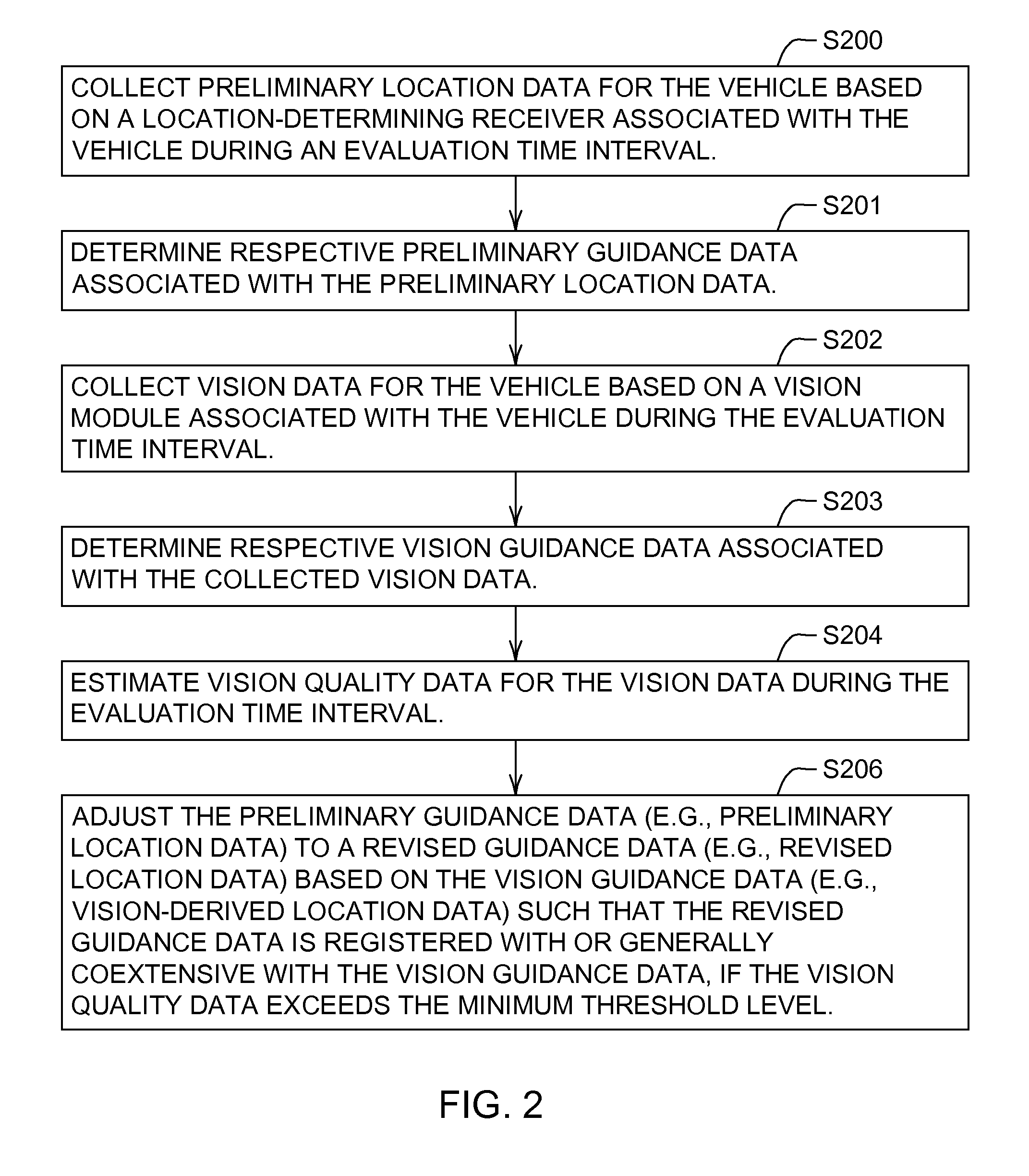
The patent describes a system that uses a receiver to collect preliminary location data for a vehicle, and a vision module to collect vision data during an evaluation time window. The system then uses a vision quality estimator to estimate the quality of the vision data and the vision guidance data. An adjuster then adjusts the preliminary guidance data based on the vision guidance data to ensure that it is registered with or generally coextensive with the vision guidance data. The technical effect of this system is to improve the accuracy and precision of location-determining receivers by using vision data to guide the preliminary guidance data.

Problems solved by technology

However, although certain GPS receivers with differential correction may have a general positioning error of approximately 10 centimeters (4 inches) during a majority of their operational time, an absolute positioning error of more than 50 centimeter (20 inches) is typical for five percent of their operational time.
Further, GPS signals may be blocked by buildings, trees or other obstructions, which can make GPS-only navigation system unreliable in certain locations or environments.

Method used


Image

  • Method and system for guiding a vehicle with vision-based adjustment
  • Method and system for guiding a vehicle with vision-based adjustment
  • Method and system for guiding a vehicle with vision-based adjustment

Examples


Embodiment Construction

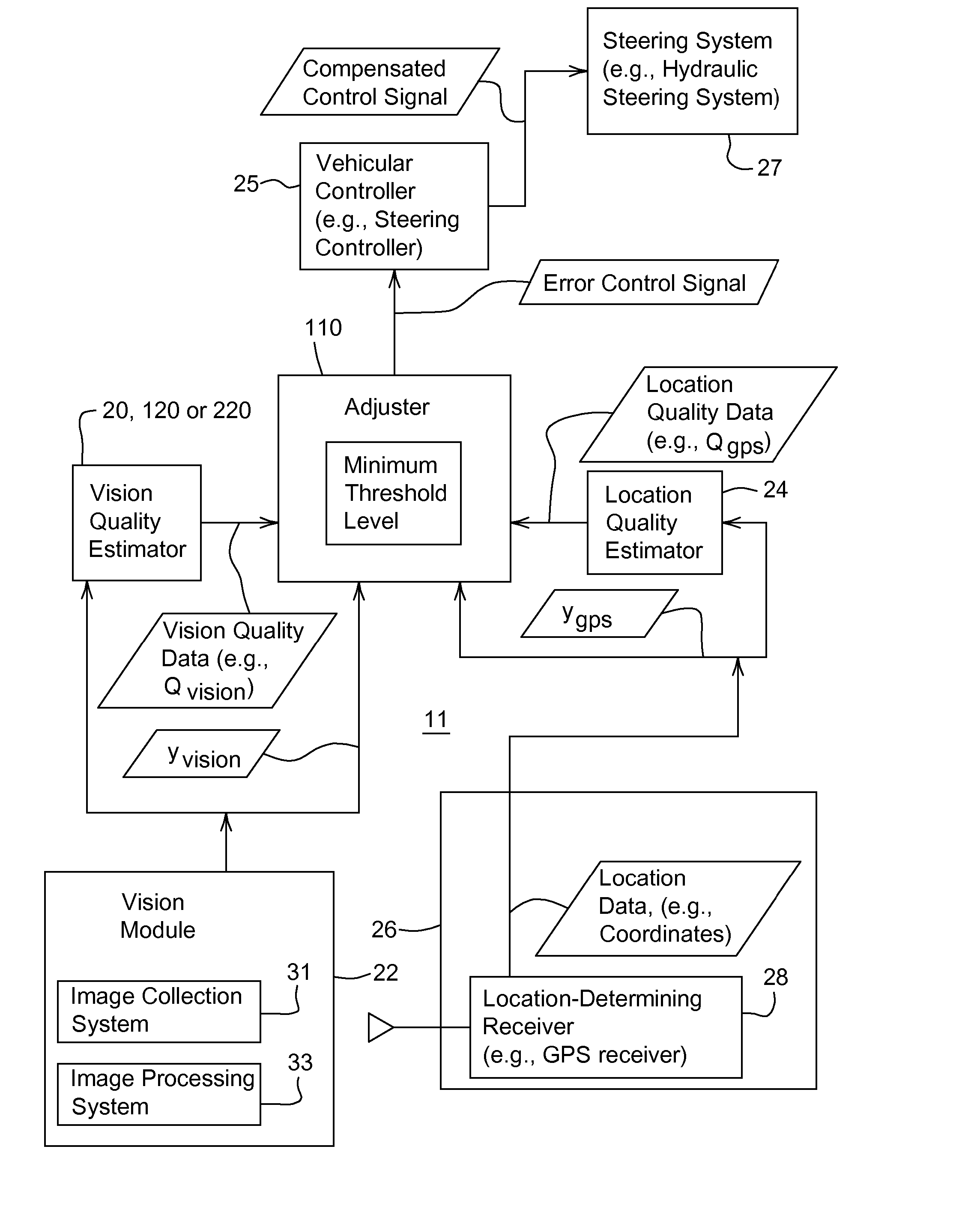
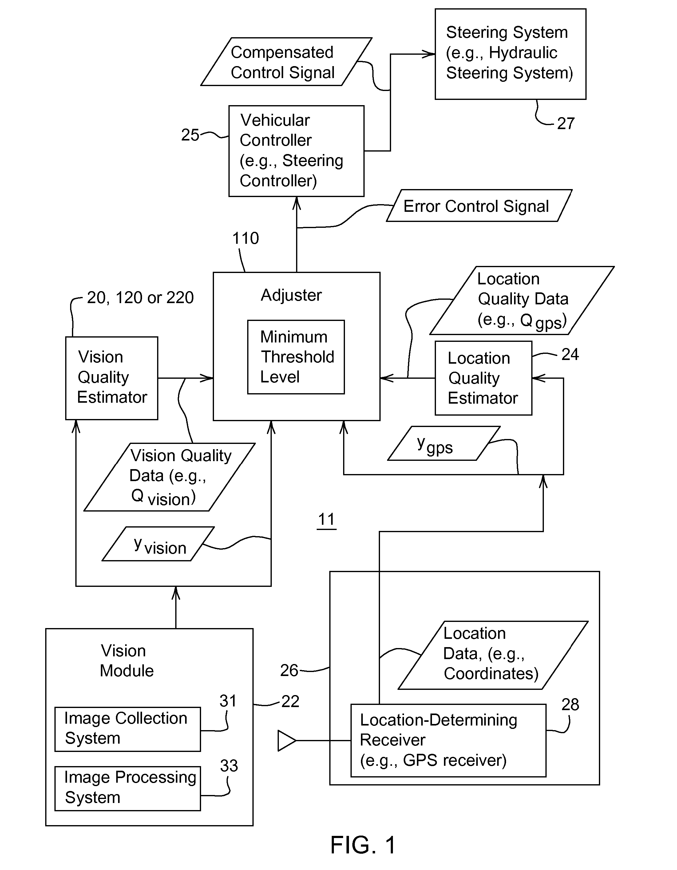
[0023]FIG. 1 is a block diagram of a guidance system 11 for guiding a vehicle. The guidance system 11 may be mounted on or collocated with a vehicle or mobile robot. The guidance system 11 comprises a vision module 22 and a location-determining receiver 28 that communicate with an adjuster 110.

[0024] The vision module 22 may be associated with a vision quality estimator (20 or 120). The location-determining receiver 28 may be associated with a location quality estimator 24. The adjuster 110 may communicate with a vehicular controller 25. In turn, the vehicular controller 25 is coupled to a steering system 27.

[0025] The location-determining receiver 28 may comprise a Global Positioning System (GPS) receiver with differential correction (e.g., a GPS receiver and a receiver for receiving a differential correction signal transmitted by a satellite or terrestrial source). The location determining receiver 28 provides location data (e.g., coordinates) of a vehicle. The location-determin...


PUM


Abstract

A preliminary guidance data is determined for the vehicle during an evaluation time window. A vision module collects vision data from a vision module during the evaluation time window. Vision guidance data is determined from the collected vision data. A vision quality estimator estimates vision quality data for at least one of the vision data and the vision guidance data during the evaluation time window. The vision quality data is based on a cross correlations and an r-squared value. An adjuster adjusts the preliminary guidance data to a revised guidance data based on the vision guidance data such that the revised guidance data is registered with or generally coextensive with the vision guidance data, if the vision quality data exceeds a minimum threshold.

Description

[0001] This is a continuation-in-part of U.S. application Ser. No. 11 / 107,114, filed Apr. 15, 2005, which claims the benefit of U.S. Provisional Application No. 60 / 641,240, filed Jan. 4, 2005 under 35 U.S.C. 119(e).FIELD OF THE INVENTION [0002] This invention relates to a method and system for guiding a vehicle with vision adjustment. BACKGROUND OF THE INVENTION [0003] Global Positioning System (GPS) receivers have been used for providing position data for vehicular guidance applications. However, although certain GPS receivers with differential correction may have a general positioning error of approximately 10 centimeters (4 inches) during a majority of their operational time, an absolute positioning error of more than 50 centimeter (20 inches) is typical for five percent of their operational time. Further, GPS signals may be blocked by buildings, trees or other obstructions, which can make GPS-only navigation system unreliable in certain locations or environments. Accordingly, th...

Claims


Application Information

Patent Timeline
Patent Type & Authority Applications(United States)
IPC IPC(8): G05D1/00
CPCA01B69/007G01S19/48G06K9/00798G05D1/0278G05D1/024G05D1/0246G06V20/588G01S19/485
Inventor HAN, SHUFENGPICKETT, TERENCE DANIELREID, JOHN FRANKLIN
Owner DEERE & CO
Learn More