
Finger-mounted suture cutter

a suture cutter and finger-mounted technology, applied in the field of surgical instruments, can solve the problems of inability to easily tire, inability to move the hand, inability to use the muscles used to oppose the fingers in this manner, etc., and achieve the effect of reducing the problem, facilitating the cutting of sutures, and facilitating the cutting

Inactive Publication Date: 2008-03-20
VALLERO ROMMEL P
View PDF11 Cites 10 Cited by
  • Summary
  • Abstract
  • Description
  • Claims
  • Application Information

AI Technical Summary

Benefits of technology

[0009]It is an object of the present invention to address the shortcomings of the prior art and to provide a cutting instrument that minimizes the problems described above. It is also an object of the present invention to provide a quicker and safer method of cutting suture and other like material.

Problems solved by technology

This hand motion is somewhat difficult to do, especially if multiple cuts need to be made in succession.
The muscles used to oppose the fingers in this manner are inherently weaker than muscles used to flex and extend the fingers and can tire easily.
The sharp edges and points of the scissors are also exposed and increase the risk of operator or patient injury should there be unwanted or unexpected movement during the suturing process.
Although this device allows cutting of thread and other similar material without any complicated movements of the finger, the cutting blade is tucked away and close to the thimble and lacks the ability to guide the thread or suture towards the cutting edge.
Delinanos' thimble mounted invention also lacks the ability to adjust to different sized fingers, which also limits its use.
This embodiment guides the suture towards the cutting edge, but does not allow the edge to get close to the suture knot and requires the use of larger, less dexterous muscles to make the cut.
Both Miklos's and Shinichi's cutters are also placed close to the finger and limits the ability to cut sutures very short as is sometimes desired, or to enable cutting in tight spaces like in the mouth or between fingers and toes.
These cutters also lack the ability to cut material unless it is pulled taut and drawn against the cutting blade.

Method used


Image

  • Finger-mounted suture cutter
  • Finger-mounted suture cutter

Examples


Embodiment Construction

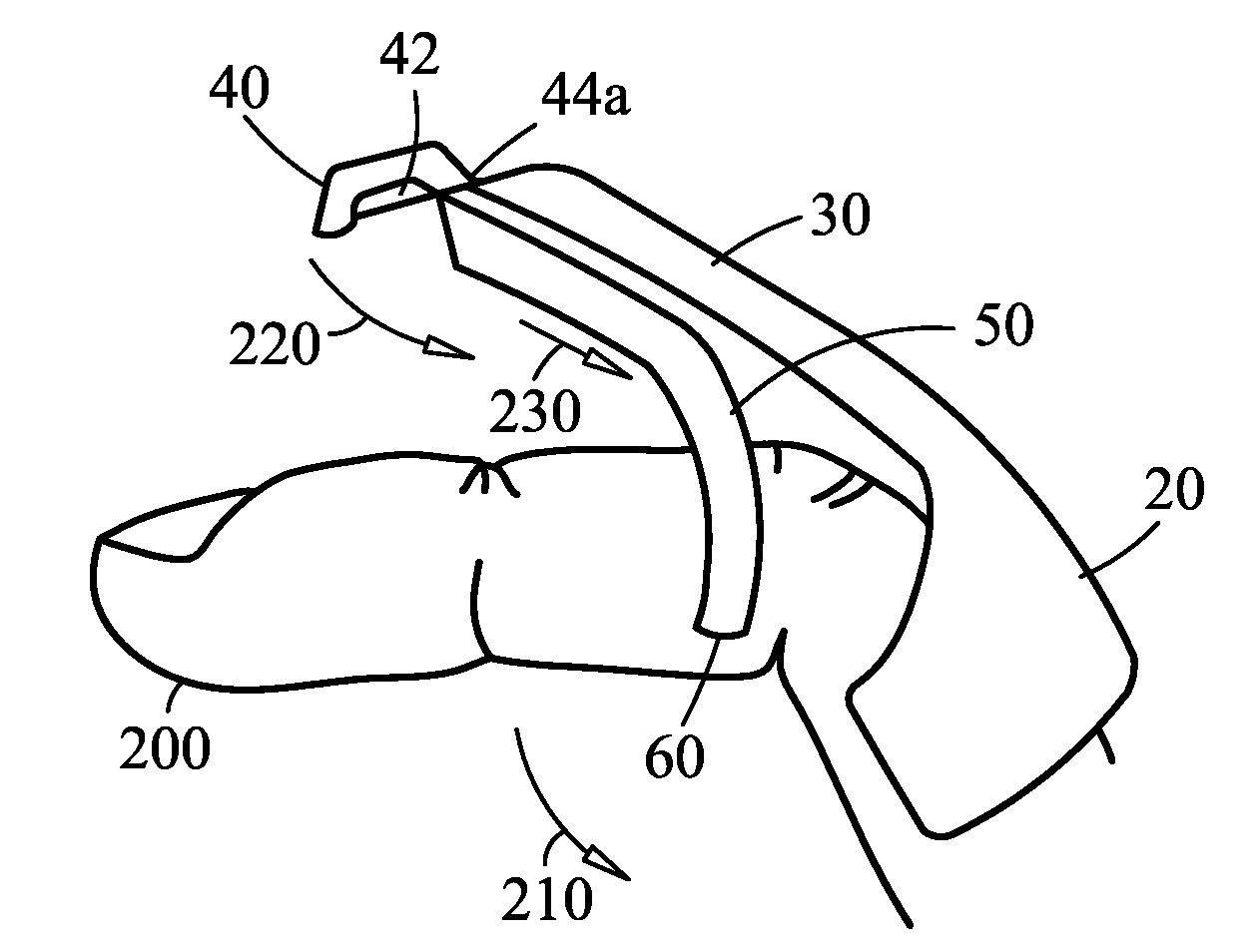
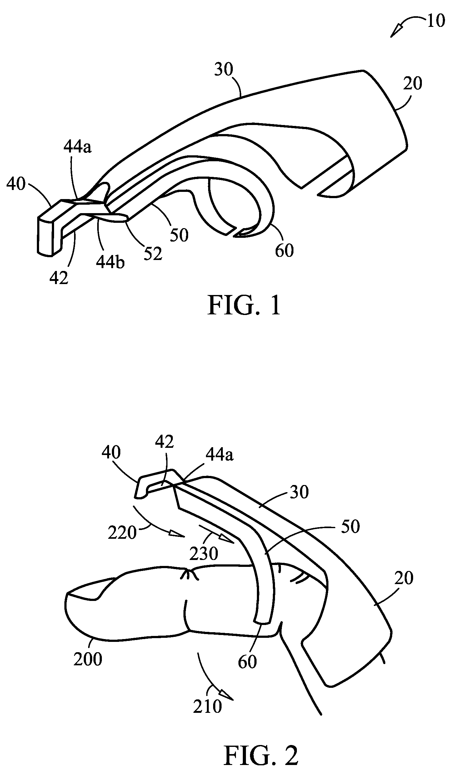
[0013]Referring to FIG. 1, the apparatus of the present invention comprises preferably a molded plastic unit 10 with an adjustable band 20 on one end designed to fit over variable finger sizes and a protruding curved arm 30 on the other end. The extended curved arm 30 allows the operator to reach into tight spaces and allows for close and precise placement of blade 42 onto a suture. At the end of the curved arm 30 is a pivoting head 40 in which a razor sharp cutting blade 42 is enclosed.

[0014]Referring to FIG. 2, blade 42 is recessed back to prevent contact with anything except a suture. Head 40 may move in a semi circular arc due to two thin, flexible plastic hinges 44a, 44b connected to the curved arm 30 and a lower arm 50. Lower arm 50 fits over a more distal portion of the finger 200 with a similar adjustable band 60 to fit variable finger sizes. Pivoting head 40 can be made to pull the cutting edge 42 against an opposing flat cutting surface 52 by flexing finger 200 and pulling...


PUM


Abstract

The present invention comprises a sterilized disposable suture cutter worn preferably on the small finger of the same hand used to hold the needle holder. The device can cut by pulling the cutting edge against a somewhat taut suture material in a slicing fashion. Alternatively, the small finger can be flexed causing the cutting edge to be drawn against an opposing flat surface in a chopping motion. This second chopping method would be useful in cutting sutures where it would be difficult or impossible to place tension onto the suture. When not being used, the device does not interfere with the normal motions necessary to place sutures.

Description

CROSS-REFERENCE TO RELATED APPLICATIONS[0001]The present application is a Non-Provisional of Provisional U.S. Patent Application Ser. No. 60 / 846,047 filed on Sep. 20, 2006 and incorporated herein by reference in its entirety.FIELD OF THE INVENTION[0002]The present invention relates to surgical instruments, in particular, to hand held devices used for suture cutting after a surgical knot is made.BACKGROUND OF THE INVENTION[0003]Surgical activities involving the stitching of tissue require that the suture be severed when a stitch has been completed. This usually requires that the operator release his / her grasp of the tool used to hold the needle, place it down somewhere within the sterile field, pick up a pair of scissors to make the cut, place down the scissors in the sterile field and re-grasp the needle holder in order to place another stitch.[0004]Because most suturing procedures require multiple stitches and multiple suture cuts, it would be desirable in situations such as those ...

Claims


Application Information

Patent Timeline
IPC IPC(8): B26D1/01A61B17/32
CPCA61B17/0467A61B2017/00438A61B17/0483
Inventor VALLERO, ROMMEL P.
Owner VALLERO ROMMEL P
Learn More