
Exhaust treatment packaging apparatus, system, and method

a technology of exhaust treatment and packaging, applied in mechanical equipment, engine components, machines/engines, etc., can solve the problems of corroding the tube material of the tube, affecting the space, and affecting the efficiency of the exhaust system,

Active Publication Date: 2008-03-20
CUMMINS FILTRATION IP INC
View PDF27 Cites 62 Cited by
  • Summary
  • Abstract
  • Description
  • Claims
  • Application Information

AI Technical Summary

Benefits of technology

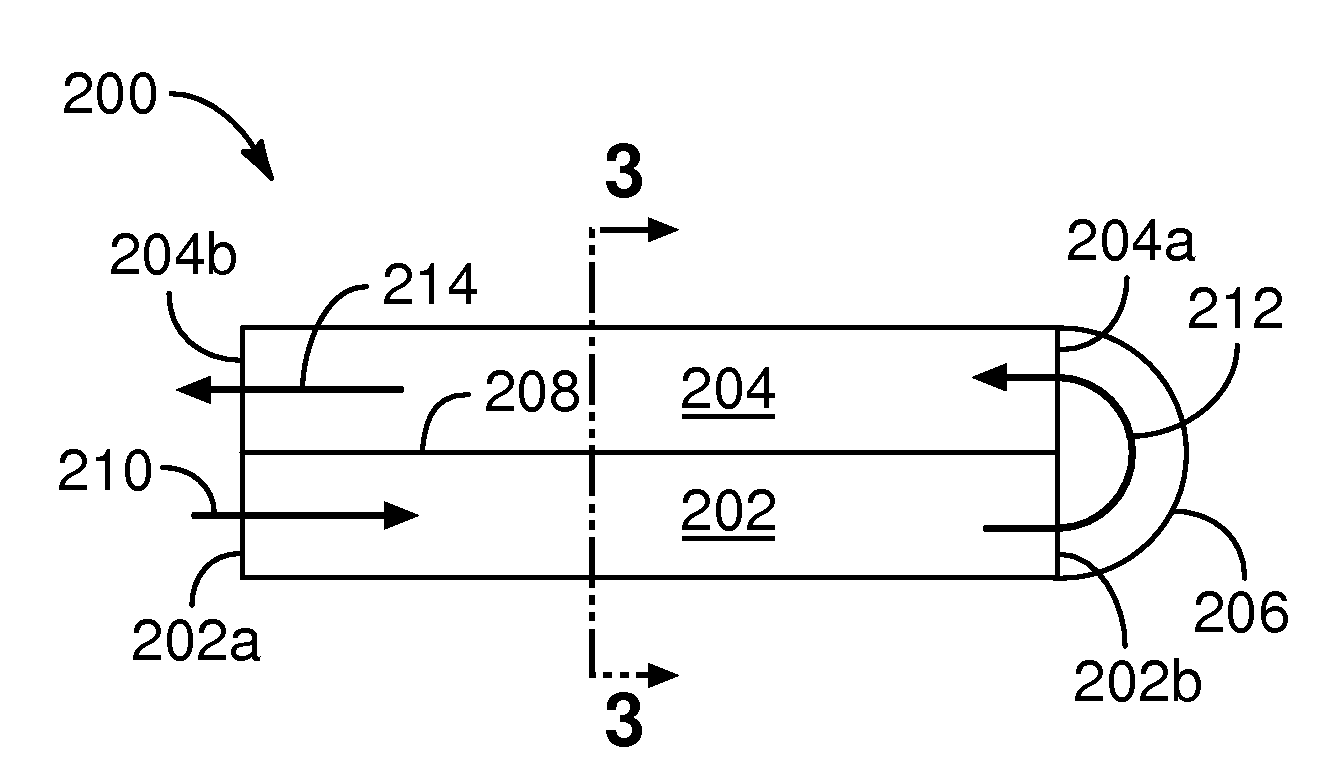
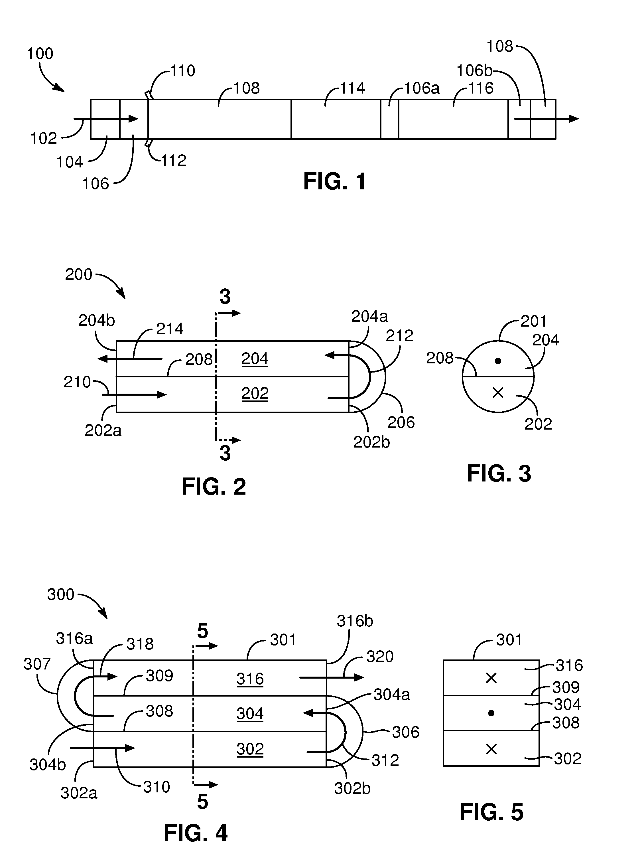
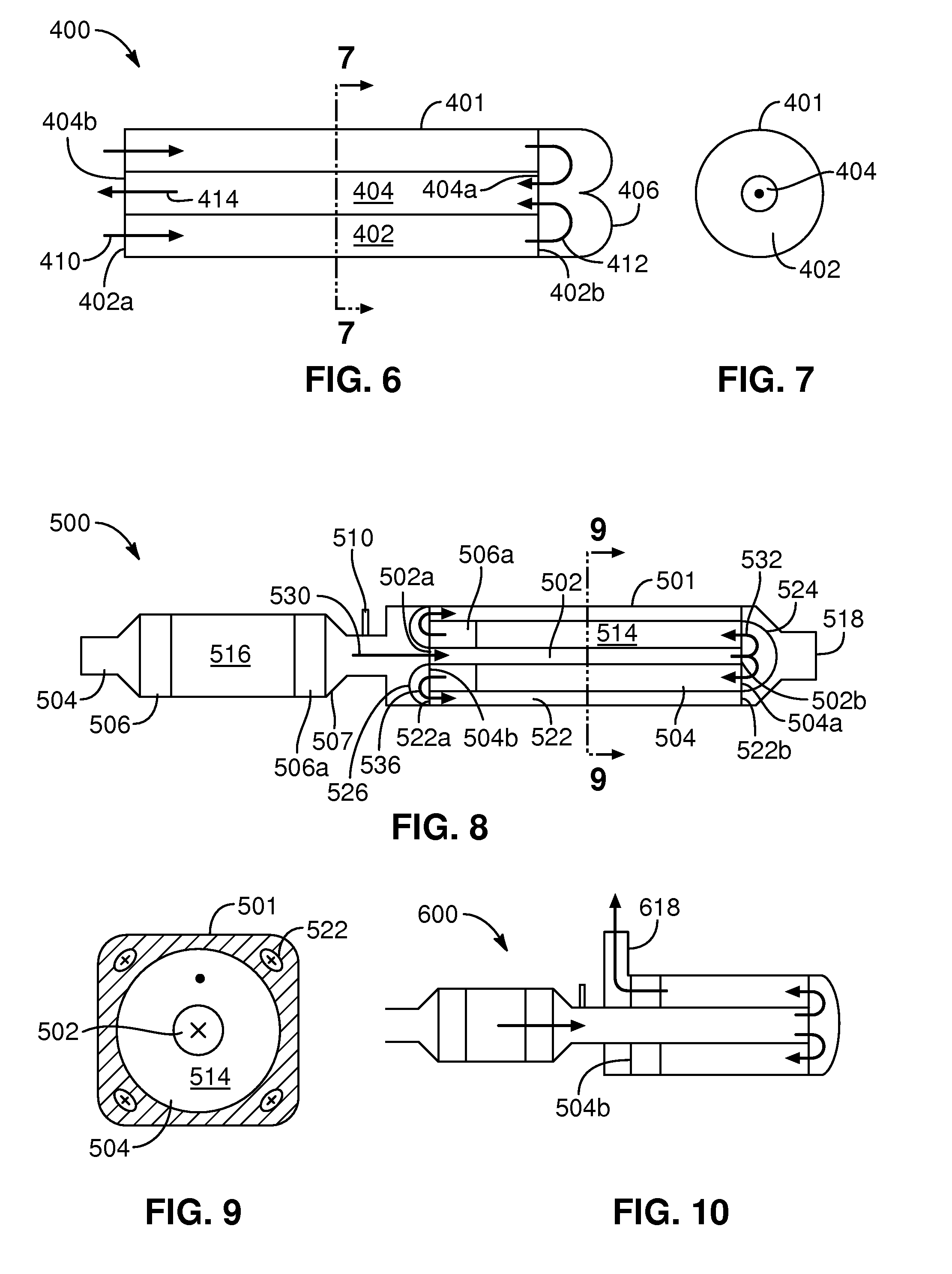
The present invention provides an exhaust treatment packaging system that overcomes shortcomings in the art by addressing the problems and needs in the art. The system includes a first passage for housing exhaust gases in a first direction, a reverse-flow mechanism for receiving the exhaust gases from the first passage and causing them to flow in a second direction opposite to the first direction, and an exhaust treatment device disposed within the second passage. The system also includes a second passage disposed next to the first passage, which receives the exhaust gases from the reverse-flow mechanism. The second passage is annular in cross-section and elongate such that its outer surface is cylindrical. The system also includes a method of treating exhaust gases by moving them, dosing them with an additive, and urging them through a first passage in a first direction, reversing their direction, and urging them through a second passage in a second direction opposite to the first direction. The system also includes a diesel exhaust gas stream treatment system with two elongate channels disposed in parallel arrangement within the housing, with one channel containing a catalytic device. The technical effects of the invention include improved exhaust gas treatment, reduced emissions, and improved system performance.

Problems solved by technology

The problem of efficient use of exhaust stream additive chemicals makes the issue of space more difficult, since many additives, after being injected or “dosed” into the exhaust stream, need to mix, undergo chemical change, be evaporated, or otherwise be modified from their original injected form before encountering exhaust treatment components such as flow-through catalytic devices or particulate filters.
Too short a distance can result in unevaporated hydrocarbon mixing with soot in the exhaust system and gumming up the oxidation catalyst.
In addition to reducing the amount of ammonia reaching the SCR device, the unevaporated urea can produce acids that corrode the tube material.
The space requirement of these additive treatments is difficult to incorporate into the limited space allocated to exhaust treatment.

Method used


Image

  • Exhaust treatment packaging apparatus, system, and method
  • Exhaust treatment packaging apparatus, system, and method
  • Exhaust treatment packaging apparatus, system, and method

Examples


Embodiment Construction

[0032]Reference throughout this specification to “one embodiment,”“an embodiment,” or similar language means that a particular feature, structure, or characteristic described in connection with the embodiment is included in at least one embodiment of the present invention. Appearances of the phrases “in one embodiment,”“in an embodiment,” and similar language throughout this specification may, but do not necessarily, all refer to the same embodiment.

[0033]The described features, structures, or characteristics of the invention may be combined in any suitable manner in one or more embodiments. In the following description, numerous specific details are provided. One skilled in the relevant art will recognize, however, that the invention may be practiced without one or more of the specific details, or with other methods, components, materials, and so forth. In other instances, well-known structures, materials, or operations are not shown or described in detail to avoid obscuring aspect...


PUM


Abstract

An exhaust treatment packaging apparatus, system, and method includes an elongate exhaust gas passage comprising an inlet for the entrance of flowing exhaust gases and an outlet for the exit of the gases. A catalytic device comprising an inlet and an outlet completely or partially overlaps the passage to reduce the length required for the system. The passage outlet is disposed adjacent the catalytic device inlet, and a flow connector connects the passage outlet to the catalytic device inlet. A particulate filter or other treatment device may be substituted for or added to the catalytic device. A doser disposed upstream of the passage doses an additive which evaporates, mixes, or otherwise undergoes change in the passage before reaching the catalytic device.

Description

BACKGROUND OF THE INVENTION[0001]1. Field of the Invention[0002]This invention relates to exhaust treatment systems, and more particularly to efficient packaging and use of those systems.[0003]2. Description of the Related Art[0004]Stricter environmental regulations in the United States and Europe are requiring the use of exhaust treatment devices such as particulate filters and / or catalytic devices on diesel engines to reduce harmful emissions including nitrogen oxides (NOx), hydrocarbons, carbon monoxide, soot, ash, and other substances. Space is usually at a premium on diesel engines and their related components, particularly on trucks or other moving vehicles, and it is desirable that the additional exhaust treatment components be compacted into as small a space as possible.[0005]The problem of efficient use of exhaust stream additive chemicals makes the issue of space more difficult, since many additives, after being injected or “dosed” into the exhaust stream, need to mix, und...

Claims


Application Information

Patent Timeline
Patent Type & Authority Applications(United States)
IPC IPC(8): F01N3/00F01N3/10
CPCF01N3/0253F01N13/0093F01N3/106F01N3/2066F01N3/2093F01N2470/10F01N2470/18F01N2470/22F01N2470/24F01N2490/06F01N2610/02F01N2610/03Y02T10/24F01N13/009F01N13/0097F01N3/035Y02T10/12
Inventor WARNER, JAYPAWSON, KENNETHVASNIER, JEAN-MARC
Owner CUMMINS FILTRATION IP INC
Learn More