Method and apparatus for determining flow

a flow rate and flow method technology, applied in the direction of liquid/fluent solid measurement, fire alarms, instruments, etc., can solve the problems of not revealing any processing operations for the signal, inaccurate flow rate, and no treatmen

Inactive Publication Date: 2008-03-20
GARRETT THERMAL SYST LTD
View PDF10 Cites 16 Cited by
  • Summary
  • Abstract
  • Description
  • Claims
  • Application Information

AI Technical Summary

Problems solved by technology

However, this empirically determined flow rate is not accurate and is corrected for variation in the propagation rate of the transmitted ultrasound pulses by deriving a correlation factor from the output signal of the second transducer.
Freund et al does not disclose any processing operations for the signa...

Method used


Image

  • Method and apparatus for determining flow
  • Method and apparatus for determining flow
  • Method and apparatus for determining flow

Examples


Embodiment Construction

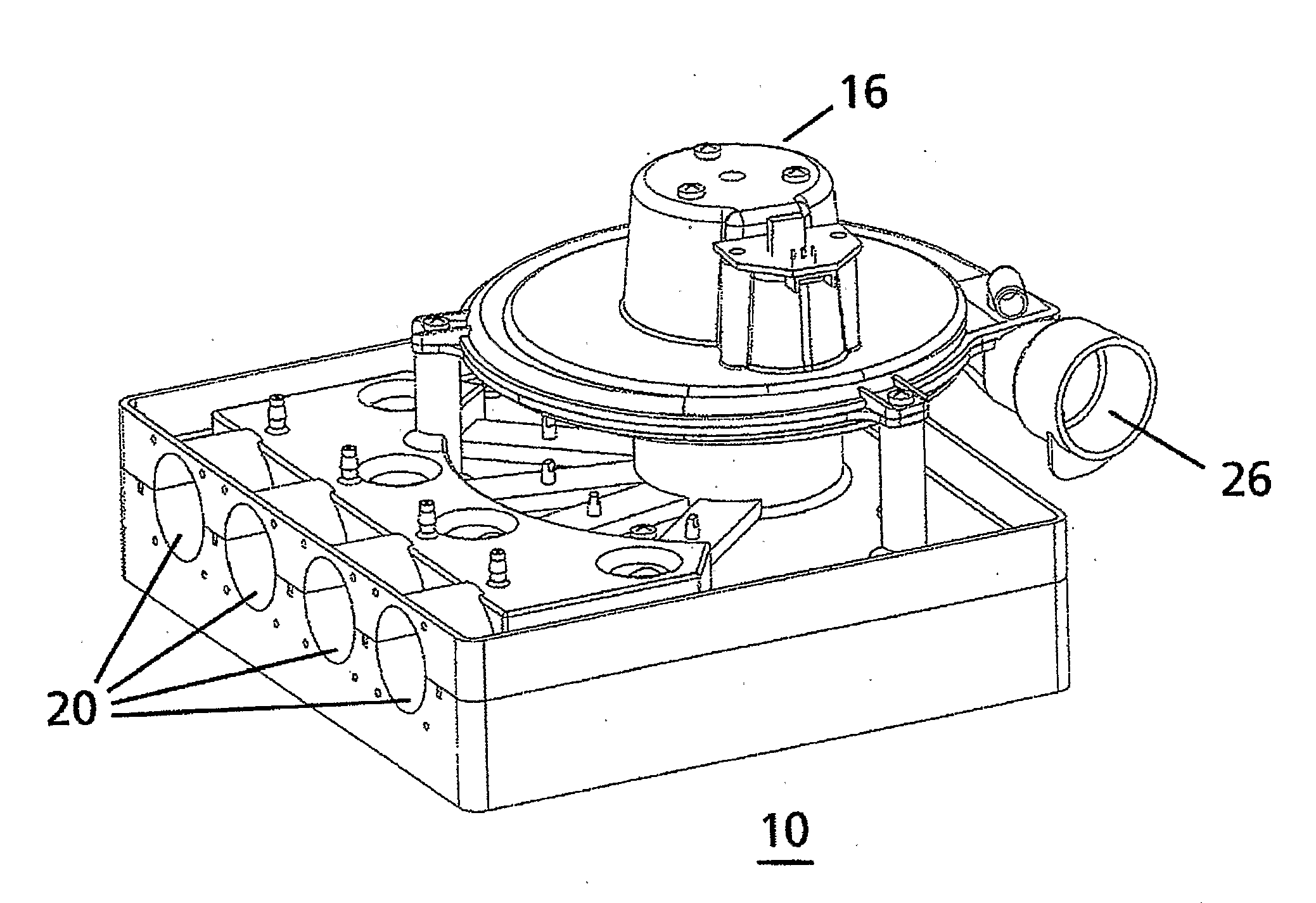
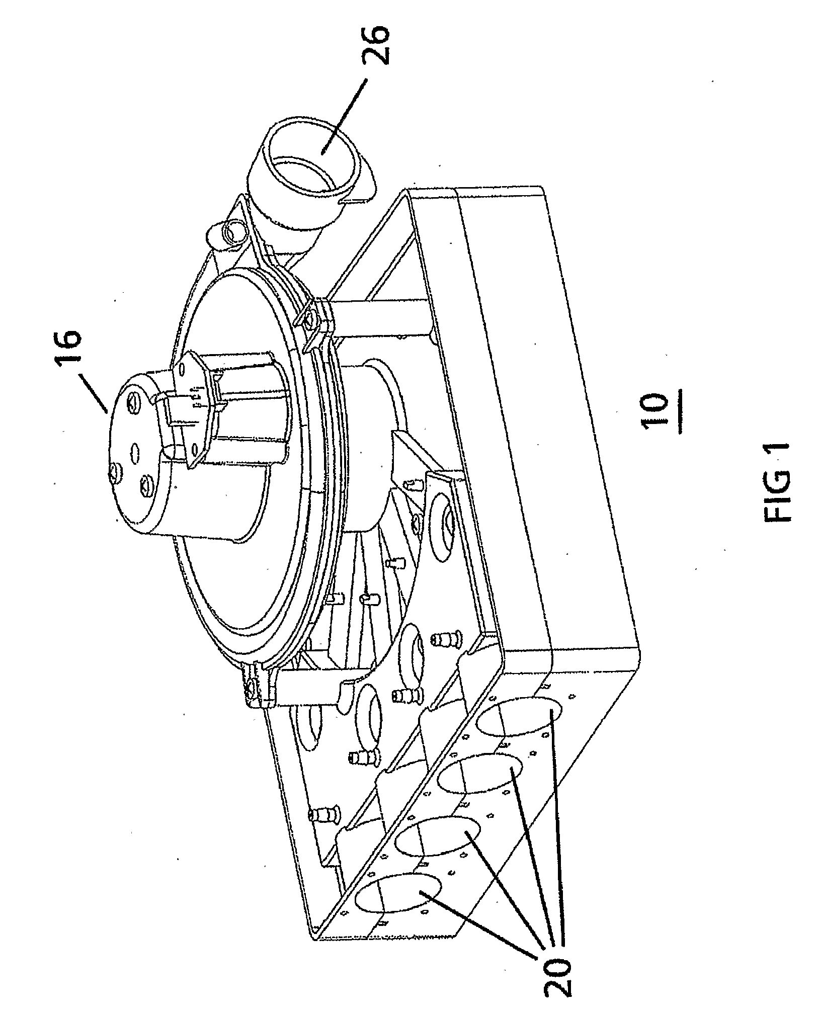
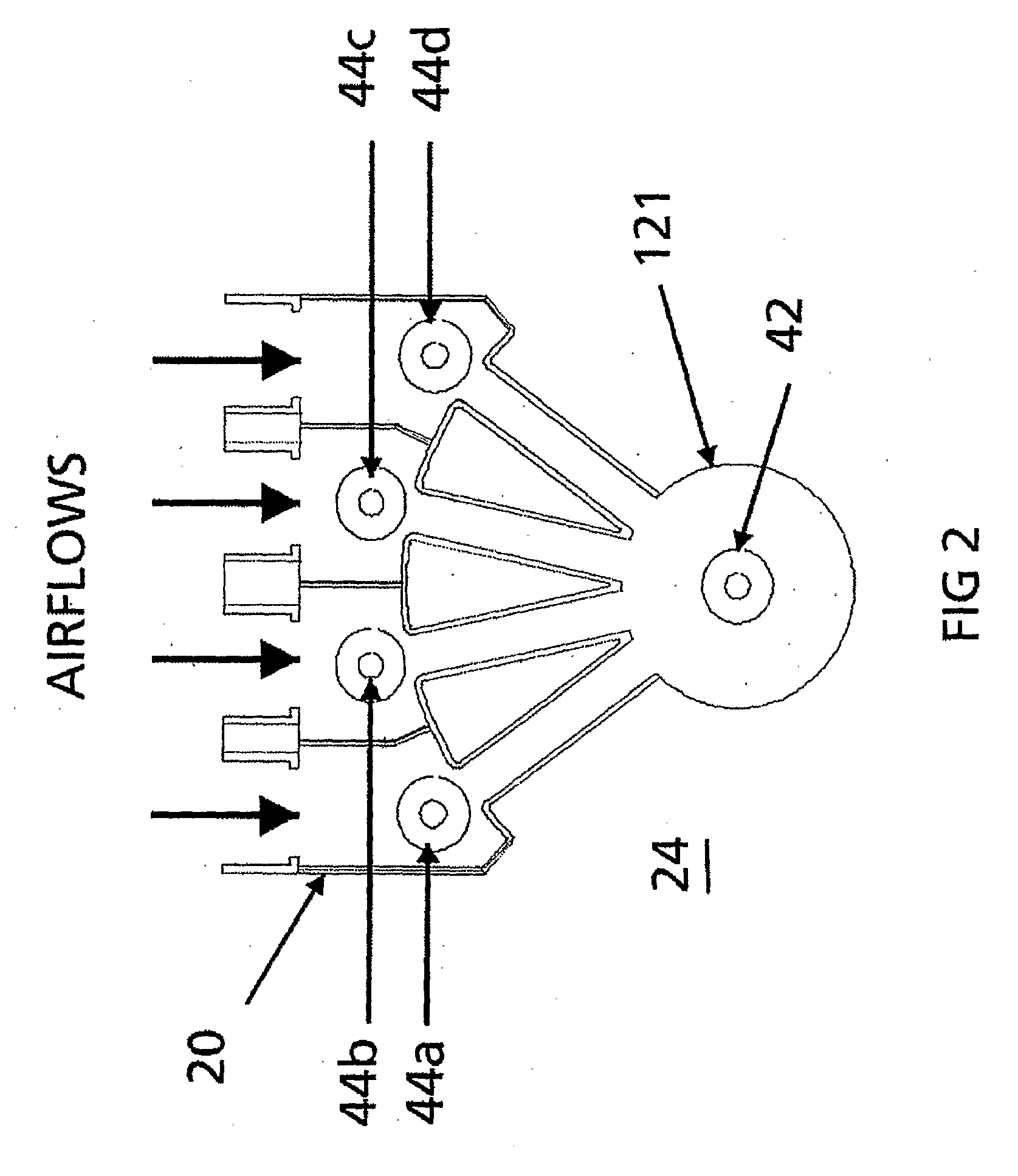
[0034] In one aspect the present invention provides a method of determining flow in an aspirated particle detector system, said system comprising a plurality of carriers in fluid communication with a particle detector, said method comprising the step of:

[0035] detecting the flow rate in at least one of the carriers comprising sensing a signal transmitted between a first and a second signal transceiver wherein the first transceiver is adapted to transceive signals in at least two of the carriers.

[0036] In one particular embodiment, the method of the present invention may further comprise the step of scanning carriers by performing or applying the step of detecting to the plurality of carriers, selectively. In one form, the selective scanning may comprise sequentially applying the step of detecting to each of the plurality of carriers.

[0037] In a preferred embodiment the step of detecting the flow rate further comprises determining the time of flight of the signal transmitted betwe...


PUM


Abstract

The present invention relates to the field of pollution monitoring equipment and in particular to aspirated particle detector systems, which detect particles in air sampled from a number of locations The present invention provides a method and apparatus for determining flow in an aspirated particle detector systems said system comprising a plurality of carriers in fluid communication with a particle detector, comprising means for detecting the flow rate in at least one of the carriers comprising sensing a signal transmitted between a first and a second signal transceiver (44a-d, 42) wherein the first transceiver (42) is adapted to transceive signals in at least two of the carriers. In a preferred embodiment, the invention relates to the use of an ultrasonic means of flow sensing within an aspirated smoke detector system.

Description

RELATED APPLICATIONS [0001] This application claims priority to Australian Provisional Patent Application No. 2004906487, filed 12 Nov. 2004 and entitled “Method and Apparatus for Determining Flow” and, the specification thereof is incorporated herein by reference in its entirety and for all purposes. FIELD OF INVENTION [0002] The present invention relates to the field of pollution monitoring equipment and in particular to aspirated particle detector systems. More particularly, the invention relates to an improvement in particle detector systems, which detect particles in air sampled from a number of locations. It will be convenient to hereinafter describe the invention in relation to the use of an ultrasonic means of flow sensing within an aspirated smoke detector system, however, it should be appreciated that the present invention is not limited to that use, only. For example, the present invention in one form relates to a method and apparatus for determining flow of a fluid. In t...

Claims


Application Information

Patent Timeline
IPC IPC(8): G01N11/00
CPCG01F1/662G08B17/10G01F1/667G08B17/113B33Y80/00
Inventor AJAY, KEMAL
Owner GARRETT THERMAL SYST LTD
Why Eureka
Try Eureka