Integrated well access assembly

a well access and assembly technology, applied in the direction of piston pumps, well accessories, fluid removal, etc., can solve the problems of increased labor and equipment expenses, unavoidable presence of this particular platform, and equipment delivery, maintenance and additional operators, so as to reduce the cost and space requirements

Inactive Publication Date: 2008-03-20
SCHLUMBERGER TECH CORP
View PDF3 Cites 17 Cited by
  • Summary
  • Abstract
  • Description
  • Claims
  • Application Information

AI Technical Summary

Benefits of technology

[0011]In one embodiment, in order to decrease the cost and space requirements inherent in oilfield equipment, an assembly for accessing a well is provided that includes a single prime mover coupled to both a positioning pump for positioning a well access line within the well, and a hydraulic treating pump for pumping fluid into the well access line.

Problems solved by technology

Each piece of equipment employed at the oilfield comes with significant operational costs.
Given that the clean out itself is a coiled tubing application, the presence of this particular platform is unavoidable.
Unfortunately, however, as noted above, an additional crankshaft driven high pressure assembly is also provided at the site to provide the required high pressure for a clean out application.
Thus, added labor and equipment expenses are presented in terms of equipment delivery, maintenance and additional operators.
The above described added expense of the crankshaft driven assembly may be quite significant.
In fact, two such pumps might barely fit back to back on an eight foot tractor trailer.
Thus, the capacity of the crankshaft driven triplex assembly is generally underutilized during well service applications.
However, the configuration and use of a significantly large crankshaft make it impractical for incorporation with the coiled tubing assembly trailer and its platform.
Furthermore, in order to carry out such an application as the above described clean out, a back-up pump is often provided in order to ensure that the coiled tubing does not become trapped within debris of the well, a possible occurrence in the case of pump failure.

Method used


Image

  • Integrated well access assembly
  • Integrated well access assembly
  • Integrated well access assembly

Examples


Embodiment Construction

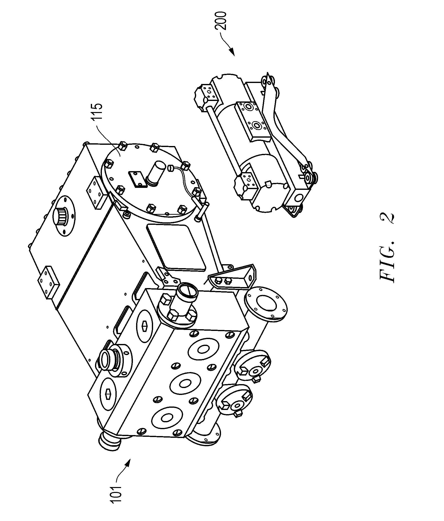
[0019]Embodiments are described with reference to certain coiled tubing operations. However, other operations may be involved which take advantage of a single prime mover to operate multiple pumps on a single stage, such as a trailer or a skid assembly. This may be accomplished, for example, by use of a hydraulic treating pump 200, as shown in FIG. 4, rather than a conventional crankshaft driven triplex pump. As shown, and discussed further herein, the hydraulic treating pump 200 lacks a rotating crankshaft of triplex pumps and therefore is much more compact and light weight.

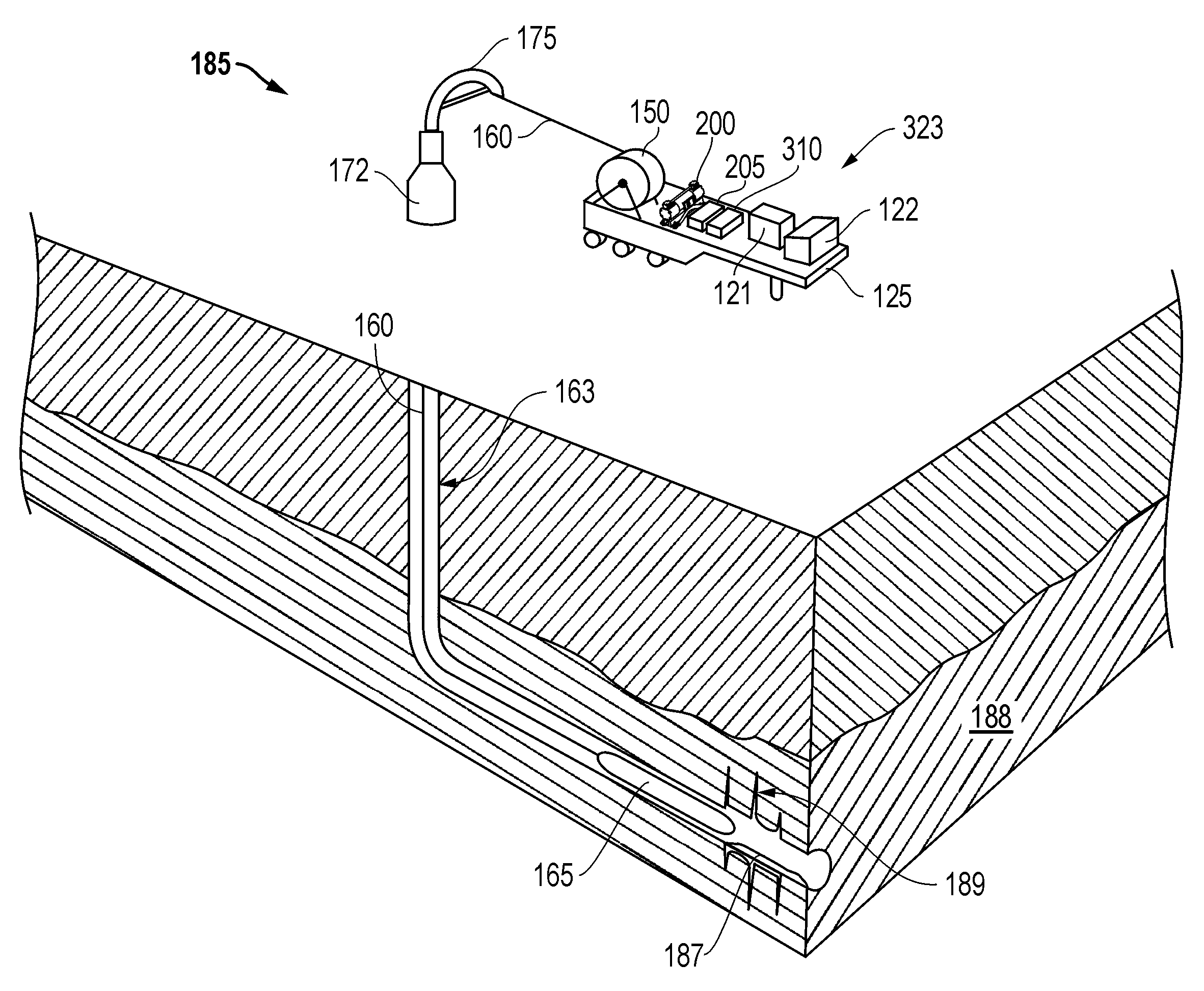
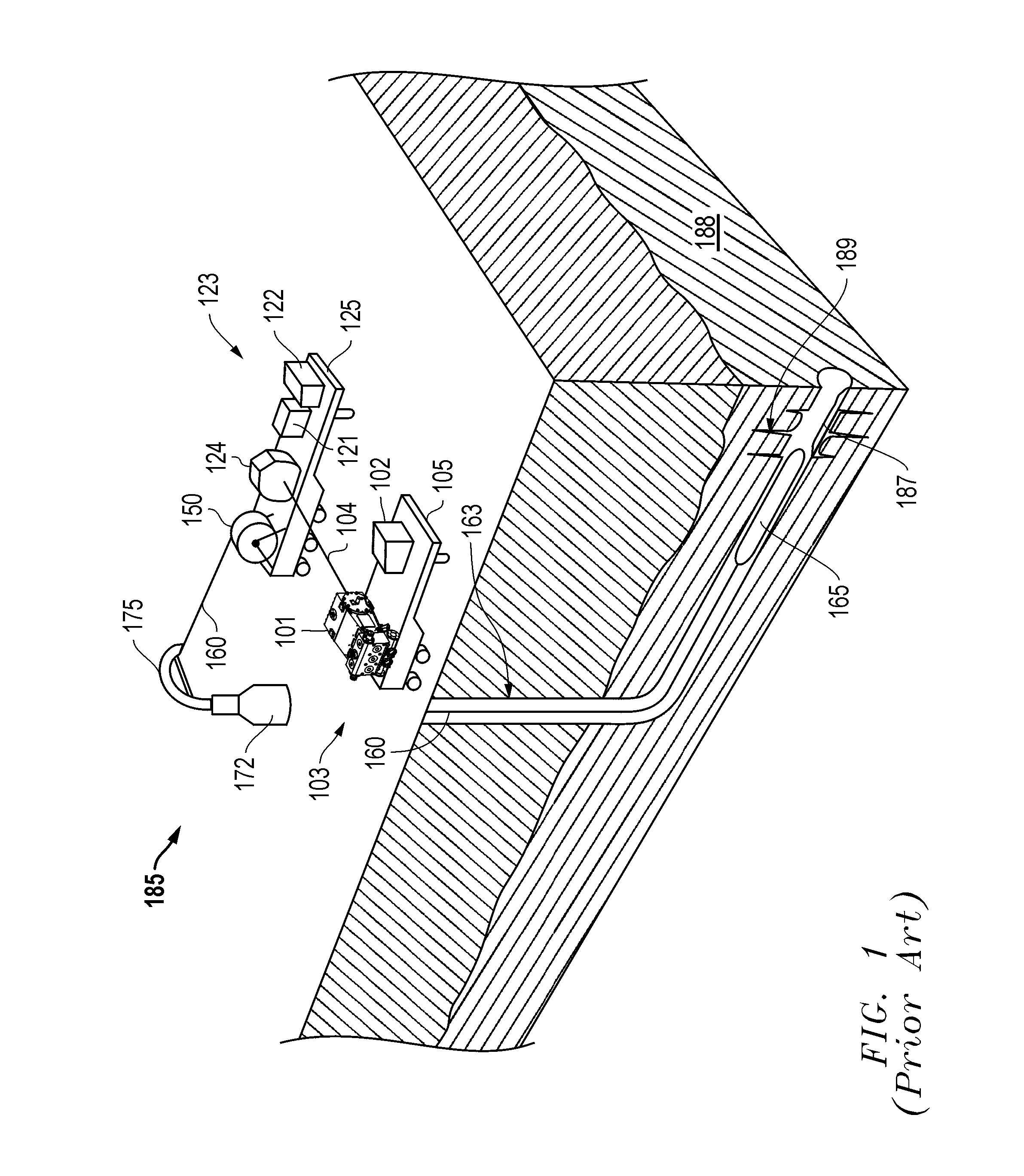
[0020]Referring now to FIGS. 1-3, a prior art employment of a coiled tubing operation at an oilfield 185 employing multiple trailer assemblies 103, 123 as shown in FIG. 1, may be viewed in light of an embodiment of a coiled tubing operation employing a single tractor trailer assembly 323 as shown in FIG. 3. This reduction in equipment at the oilfield is made possible by the employment of an embodiment of a hydra...


PUM


Abstract

An integrated well access assembly. The assembly may be a coiled tubing unit with integrated pumping capability. However, other types of assemblies for oilfield operations may be employed. Regardless, the assembly may include a single prime mover to operate multiple pumps from a single trailer platform. This may be achieved by replacement of a conventional crankshaft driven pump or other significantly massive pump with a smaller hydraulic pump of sufficient pumping capacity. This replacement allows for a reduction in the amount of capital equipment required at the oilfield for a given operation. Thus, in turn, manpower and other maintenance expenses may similarly be reduced for the operation.

Description

CROSS-REFERENCE TO RELATED APPLICATION[0001]This application claims priority under 35 U.S.C. 119(e) to U.S. Provisional Application Ser. No. 60 / 825,784, filed on Sep. 15, 2006, which is incorporated herein by reference.BACKGROUND[0002]Embodiments described relate to the employment of pumps at an oilfield for a variety of operations. In particular, embodiments of hydraulic pump assemblies for trailer delivery and employment are described.BACKGROUND OF THE RELATED ART[0003]Coiled tubing applications may be employed at an oilfield wherein a spool of pipe is slowly straightened and advanced into a well via various pump assemblies. For example, a coiled tubing application may be employed at a well in order to clean out sand or other undesirable debris within the well, perhaps at its terminal end. Similarly, a variety of other line driven applications may be directed to a well for management or treatment thereof.[0004]In order to achieve such a clean out as described above, a coiled tubin...

Claims


Application Information

Patent Timeline
Patent Type & Authority Applications(United States)
IPC IPC(8): E21B43/16
CPCE21B43/25F04B47/04F04B47/00F04B9/113
Inventor SHAMPINE, ROD
Owner SCHLUMBERGER TECH CORP
Why Eureka
Try Eureka