Shoe brake for an elevator drive

Inactive Publication Date: 2008-03-20
INVENTIO AG
View PDF6 Cites 0 Cited by
  • Summary
  • Abstract
  • Description
  • Claims
  • Application Information

AI Technical Summary

Benefits of technology

[0005] The present invention is a shoe brake having brake shoes with brake elements carrying brake linings that are measurably mounted to the shoe. The positioning of the brake elements with respect to the shoe to which it is mounted is settable, thus allowing the orientation of the brake linings to be adjusted.
[0006] The advantages achieved by the invention are substantially to be seen in that an optimum setting of the brake linings on the brake drum can be achieved by the brake elements according to the invention. With an optimum setting of the brake linings, small brake moment adjustments can be made in the final checking at the factory. In addition, tolerances of all brake parts can be accounted for, wherein also wider tolerances can be accommodated. Wider tolerances in turn mean cheaper production of the brake parts. In addition, it is advantageous that the brake elements are easily releasable from the brake shoes, because they cannot be fixed by either abrasion dust or by contamination. The shape of the brake element and the cut-out at the brake shoe guarantees even after long operating times a precise placing of the brake elements on the brake shoes.

Problems solved by technology

The complicated production of the groove-shaped cut-outs is disadvantageous.
Moreover, the brake elements can stick in the cut-outs due to contamination and abrasion dust.

Method used


Image

  • Shoe brake for an elevator drive
  • Shoe brake for an elevator drive
  • Shoe brake for an elevator drive

Examples


Embodiment Construction

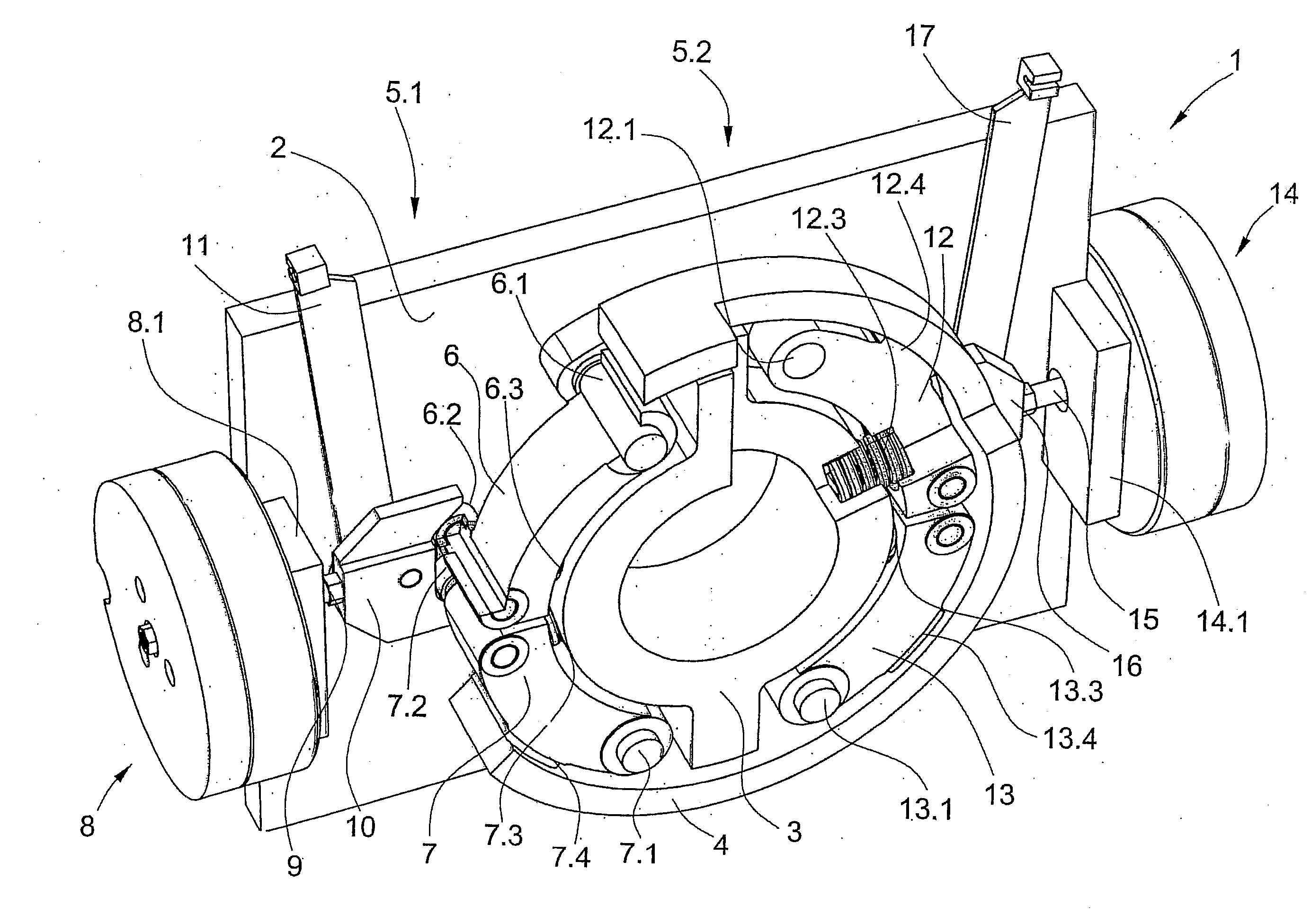
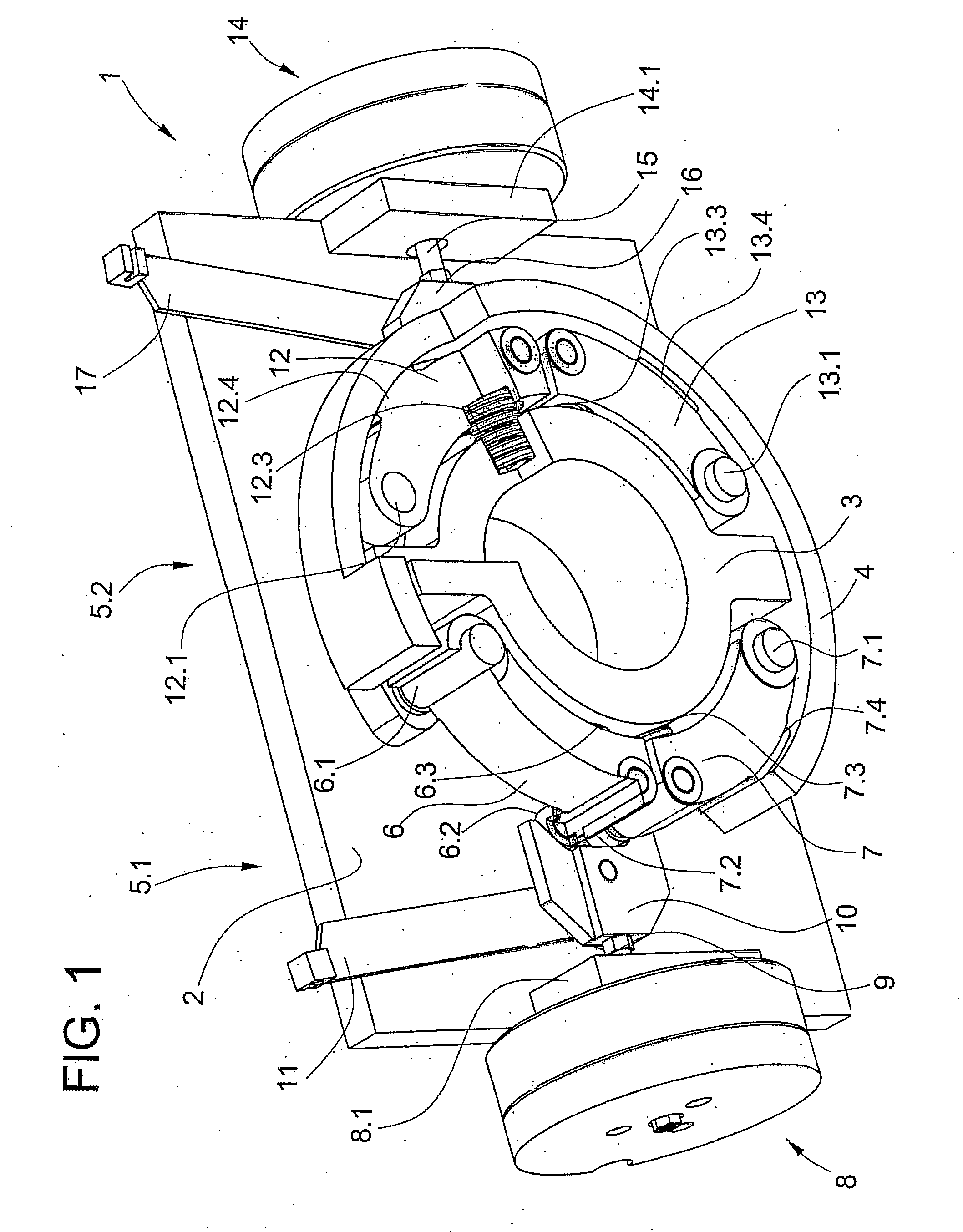
[0014]FIG. 1 is a perspective illustration of an internal shoe brake consisting of a housing plate 2, a housing ring 3, a brake drum 4 and two brake halves 5.1, 5.2 of identical construction. The brake drum 4 can be, for example, part of a drive pulley. The lefthand brake half 5.1 comprises an upper brake shoe 6 and a lower brake shoe 7. The upper brake shoe 6 is mounted at an upper brake bearing 6.1 and has at the opposed free end an actuating roller 6.2, and is pressed against the brake drum 4 by means of a compression spring 6.3 supported by the housing ring 3. The upper brake shoe 6 is illustrated in section, for which reason its brake lining is not apparent in FIG. 1. The section also runs through the roller axis at which the actuating roller 6.2 is arranged. The lower brake shoe 7 is constructed in mirror image to the upper brake shoe 6. Parts of the lower brake shoe are provided with the following reference numerals: shoe bearing 7.1, actuating roller 7.2, compression spring ...


PUM


Abstract

A shoe brake has a brake element for generating a braking force has at least one brake element that is adjustably settable relative to the brake shoe. The brake element may include an arcuate or segment-shaped base plate that fits in a corresponding arcuate or segment-shaped recess in the brake shoe and is adjustably mounted to the brake shoe by a pair of side panels.

Description

[0001] The invention relates to a shoe brake for a lift drive with at least two brake shoes, which generate a braking force at a brake drum and are releasable. The present application is a Continuation of PCT / CH2006 / 000134, filed 3 Mar. 2005.BACKGROUND OF THE INVENTION [0002] An internal shoe brake with two brake shoes has become known from the specification of JP 57107443. Two brake elements are provided per brake shoe, wherein a cut-out into which the brake element is insertable is provided at the brake shoe for each brake element. The brake element consists of a base plate carrying a brake lining, wherein the brake element fits into the shape on the arc of the brake shoe. The brake element inserted into the cut-out in the brake shoe is fixed in place at the brake shoe by means of clips. [0003] The complicated production of the groove-shaped cut-outs is disadvantageous. Moreover, the brake elements can stick in the cut-outs due to contamination and abrasion dust. [0004] The presen...

Claims


Application Information

Patent Timeline
IPC IPC(8): F16D51/18
CPCB66D5/08
Inventor SCHNEIDER, MARCEL
Owner INVENTIO AG
Why Eureka
Try Eureka