
Devices to shift the stops of rail vehicle bodies with bogies on curves and rail vehicle body with bogies

a technology for rail vehicles and stops, which is applied in the direction of bogies, wheel axle self-adjustments, railway components, etc., can solve the problems of swiveling in the same direction, the body tends to tilt towards the outside, and the centrifugal force is very small, so as to achieve the effect of widening the body

Inactive Publication Date: 2011-12-08
TALGO COMPANY
View PDF4 Cites 2 Cited by
  • Summary
  • Abstract
  • Description
  • Claims
  • Application Information

AI Technical Summary

Benefits of technology

[0005]Therefore, the purpose of this invention is to provide devices to shift the stops of the bodies of a rail vehicle on curves that succeed in limiting the lateral shift of the body towards the inside of the curve with respect to the bogie and, consequently, make it possible to design wider bodies. In addition, the corresponding rail vehicle bodies are provided with bogies that incorporate these devices.
[0011]With these configurations, the stops of the body can be shifted towards the inside of the curve when the body is in this curve, thus limiting the lateral movement towards the inside of the curve when this body enters the curve.
[0012]Another advantage of the device in the invention is that, by making it possible to design wider bodies, the traveler has more space in the interior compartment.

Problems solved by technology

Moving equipment in general, when running on a curved track or rail, are naturally subjected to a lateral thrust towards the outside thereof (due to the centrifugal force) which, in the case of railway vehicles, leads to a tendency to tilt towards the outside and for the bodies to swivel in the same direction.
When running along a curve at low speed, especially vehicles equipped with pendular suspension, the centrifugal force is very small and does not offset the natural movement towards the inside of the curve that, for example, is characteristic of this suspension; therefore, in practice, the body shifts towards the inside of the curve.

Method used


Image

  • Devices to shift the stops of rail vehicle bodies with bogies on curves and rail vehicle body with bogies
  • Devices to shift the stops of rail vehicle bodies with bogies on curves and rail vehicle body with bogies
  • Devices to shift the stops of rail vehicle bodies with bogies on curves and rail vehicle body with bogies

Examples


Embodiment Construction

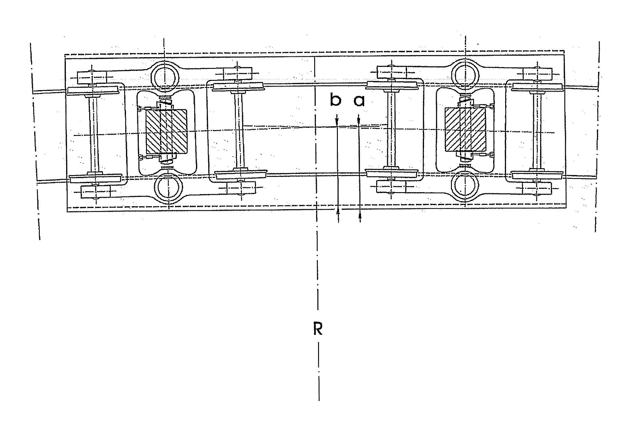
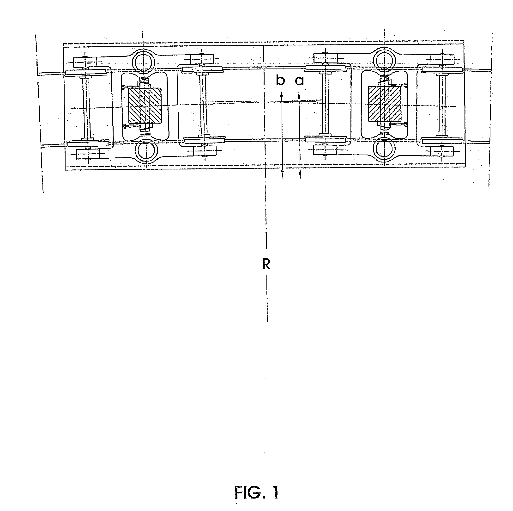
[0023]FIG. 1 shows a ground plan of a body or coach of a rail vehicle with bogies when it is traveling along a curve. The bogies adapt to the curve and form a certain angle with the body axle, as seen in the figure.

[0024]The solid line schematically represents the position of the outside edge of the body when the body has shifted towards the inside of the curve. If the lateral edge of the coach located on the inside of the curve is similar to a string with a circumference of radius R (that corresponding to the curve of the inside rail), the distance indicated as “a” in the figure would be the distance of the string to the circumference arch, called sagitta. This distance (the sagitta) limits the width of the body on the inside of the curve.

[0025]The dashed line represents the position of the body in which the device of this invention has been implemented to shift the stops of the rail bodies or coaches with bogies when they are entering a curve. As we can see, the lateral edge of th...


PUM


Abstract

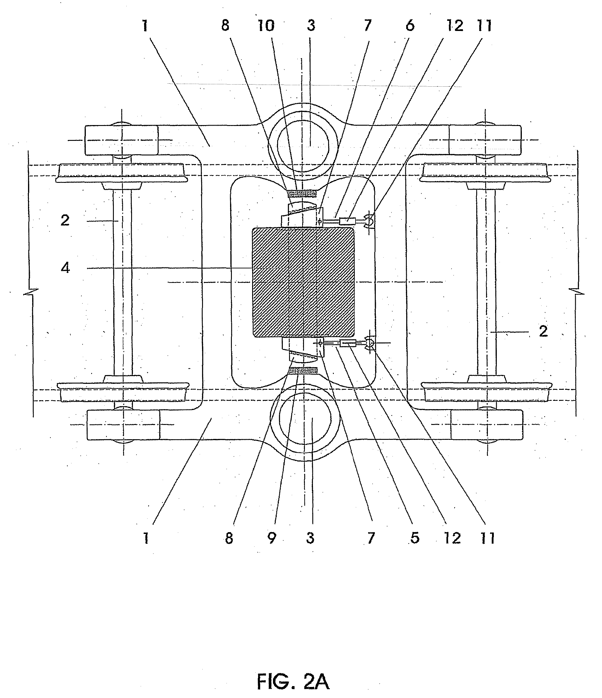
Devices to shift the stops (8) of rail vehicle bodies or coaches with bogies on curves and rail vehicle body with bogies. The devices are provided in an interior cavity of the frame of the bogies whose lateral edges each have a separate stop (9, 10) and that houses a lower projecting part (4) of the body. In one embodiment, on the front edge of the interior cavity of the frame (1) of the bogie, there is a pair of joints (11) from each of which a rod (5, 6) leads backwards and each of these is joined to a separate slider (7) by means of joints. The sliders (7) are able to move on guides located on the respective lateral surfaces of the lower projecting part (4) of the body, and the sliders (7) are wedge shaped with a guide located on their surface in the form of an inclined plane. The stops (8) of the body are coupled, at their respective inside surfaces, to the guides located on the respective sliders (7); the stops (8) of the body are joined together by transversal connection means (15).

Description

BACKGROUND[0001]This invention refers to devices to shift the stops of rail vehicle bodies or coaches with bogies when they are entering a curve, and to a rail vehicle body with bogies.[0002]Moving equipment in general, when running on a curved track or rail, are naturally subjected to a lateral thrust towards the outside thereof (due to the centrifugal force) which, in the case of railway vehicles, leads to a tendency to tilt towards the outside and for the bodies to swivel in the same direction. The pendular type suspension developed by the applicant for the family of Pendular Talgo trains (which is described, for example, in the applicant's Spanish patent 424615 as “pendular suspension system”) succeeded in reversing the direction of this swivel such that, in these trains, the vehicle bodies, when running along curves, naturally tilt “towards the inside” of the curves. This makes it possible to considerably reduce the lateral force to which people who are traveling inside the veh...

Claims


Application Information

Patent Timeline
Patent Type & Authority Applications(United States)
IPC IPC(8): B61F5/22B61F3/00
CPCB61F5/38B61F5/22
Inventor LOPEZ GOMEZ, JOSE LUIS
Owner TALGO COMPANY
Learn More