
Calibration of vehicle object detection radar with inertial measurement unit (IMU)

a vehicle object and measurement unit technology, applied in the direction of instruments, vehicle components, measurement devices, etc., to achieve the effect of large quantities and excellent quality

Pending Publication Date: 2022-06-16
PRECO ELECTRONICS LLC
View PDF0 Cites 0 Cited by
  • Summary
  • Abstract
  • Description
  • Claims
  • Application Information

AI Technical Summary

Benefits of technology

The patent text describes a technology that allows for easy and effective calibration of radar systems, even if they are mounted at wider tolerances. This results in savings of time, effort, and expense. The technology also allows for the use of commercially-available IMUs, even if not all functions are planned to be used, as long as they are of reasonable quality and quantity. This is economically advantageous in many embodiments.

Problems solved by technology

Also, it may account for errors due to movement / displacement of the radar object-detection package resulting from impact damage, or errors resulting from wear-and-tear or failure of any of the securement components for the radar package on a side of the vehicle or trailer.
Also, it may account for errors resulting from a change of height of the vehicle due to different suspensions, different tires, or adjustable height settings for the vehicle or trailer or their suspensions.

Method used


Image

  • Calibration of vehicle object detection radar with inertial measurement unit (IMU)
  • Calibration of vehicle object detection radar with inertial measurement unit (IMU)
  • Calibration of vehicle object detection radar with inertial measurement unit (IMU)

Examples


Embodiment Construction

Referring to the Figures:

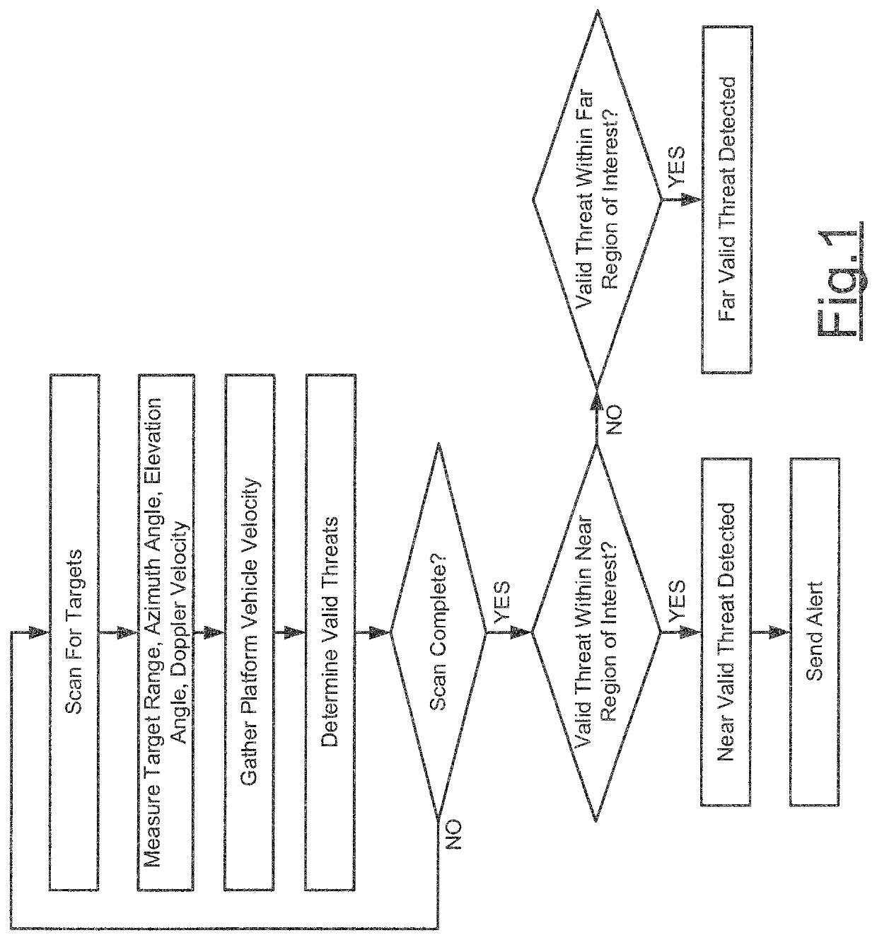
[0062]In the generalized schematic flow-chart diagram of FIG. 1, there are depicted in outline form several process steps, which a reasonably-skilled person in the art of vehicle object detection radar systems may understand and utilize for radar-based object detection. Said reasonably-skilled person in the art also will understand, once this document and the drawings have been reviewed, how to incorporate, into the process of FIG. 1 and the equipment represented by FIG. 1 and / or known in this field, methods and apparatus according to embodiments of the invention for practicing improved calibration of a radar sensor system and the resulting improved on-going operation of the radar sensor system.

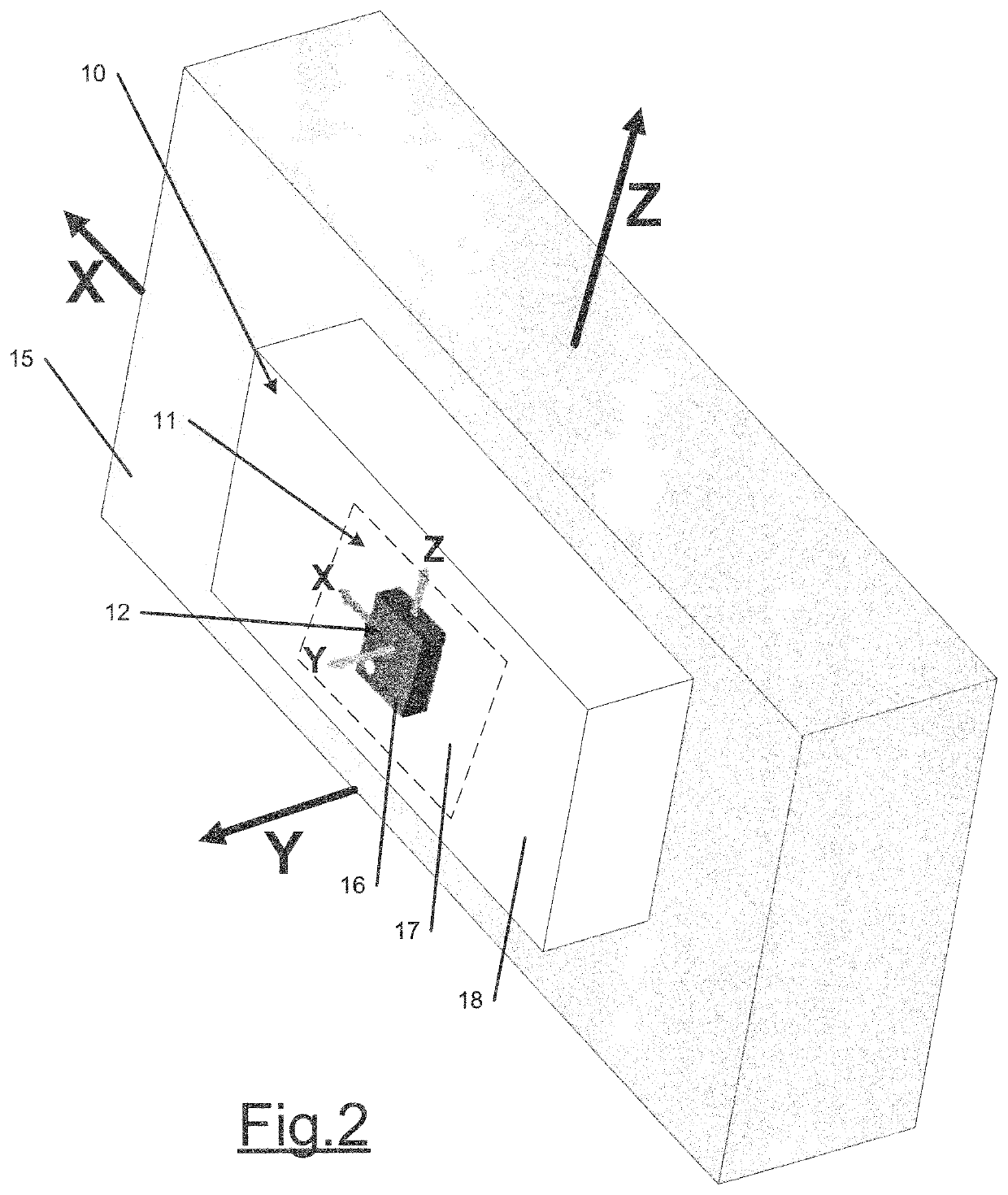
[0063]In the schematic top detail perspective left side view of FIG. 2, radar object-detection sensor package (or “unit”) 10 with built-in IMU 12 is attached to vehicle left side surface 15. The package 10 comprises IMU 12 having exterior face 16 and being operatively...


PUM


Abstract

The disclosed technology is a vehicle object detection radar system incorporating an inertial measurement unit (IMU). The IMU may obtain input signals of, or relating to, for example, relative motion, acceleration, object detection angle, sway and vibration of the vehicle and / or any towed trailer, and process them for relay to the vehicle operator as operating information and possibly alarms. Also, the obtained IMU signals may be relayed directly to the vehicle's object detection radar systems and central control for automatic adjustment and control thereof.

Description

DESCRIPTION[0001]This application claims benefit of Provisional Application Ser. No. 63 / 123,730, filed Dec. 10, 2020, entitled Calibration of Vehicle Object Detection Radar With Inertial Measurement Unit (IMU), and claims benefit of Provisional Application Ser. No. 63 / 123,777, filed Dec. 10, 2020, entitled Operation of Vehicle Object Detection Radar With Inertial Measurement Unit (IMU), the entire disclosures of both Provisional Applications being incorporated herein by this reference.BACKGROUND OF THE DISCLOSED TECHNOLOGYField of the Disclosed Technology[0002]This disclosed technology relates generally to vehicle object detection radar systems. More specifically, this disclosed technology relates to such radar systems incorporating an inertial measurement unit (IMU) to detect, and if necessary, enable the vehicle's operator or the vehicle's automatic monitoring and control systems to adjust to issues resulting from inaccurate installation of, or impact damage to, for example, the r...

Claims


Application Information

Patent Timeline
IPC IPC(8): G01S7/40G01S13/931G01C21/16
CPCG01S7/40B60R11/02G01C21/16G01S13/931G01S2013/9315G01S2013/932G01S2013/93274G01S7/403G01S7/4034G01S13/86B60W40/02B60W40/11B60W40/112B60W40/114B60W50/06B60R2011/004B60W2420/408
Inventor COLE, JONATHAN PAULFIX, JONATHAN EDWARD
Owner PRECO ELECTRONICS LLC
Learn More