
Signal detection

a signal detection and signal technology, applied in the field of signal detection methods and apparatuses, can solve the problems of small changes in the range d, the order of the wavelength of the carrier frequency, and the inability to discern, so as to achieve the effect of less expensive and wide tolerances

Inactive Publication Date: 2006-12-19
MITSUBISHI ELECTRIC CORP
View PDF12 Cites 6 Cited by
  • Summary
  • Abstract
  • Description
  • Claims
  • Application Information

AI Technical Summary

Benefits of technology

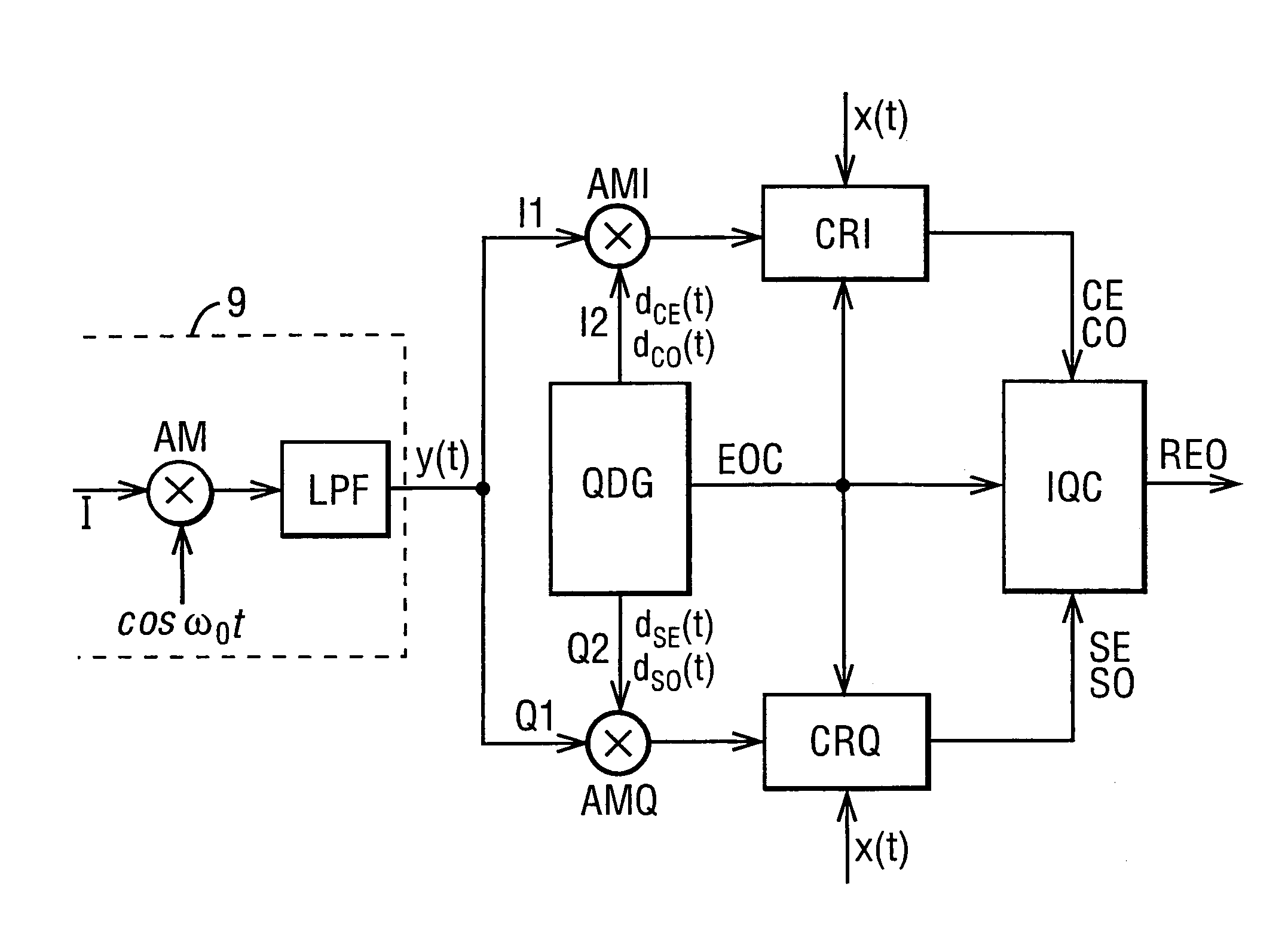
[0028]Such an arrangement avoids the need for determining the value of the frequency modification (e.g. Doppler shift) but enables the rapid detection of any target signal incorporating a frequency modification of interest, using a simple structure. The above-mentioned arrangement is thus particularly useful in applications where it is sufficient to discriminate between stationary obstacles and obstacles moving with specified velocities, and for applications in which obstacles are placed into a number of classes according to obstacle velocity, for example zero / low, moderate / average, high / very high.
[0041]Although the present invention is being described primarily in the context of detection of obstacles which produce a Doppler shift in a reflected signal, the invention is applicable also in other areas. For example, the invention is applicable to communication systems in which the local oscillators in the transmitter and receiver may not be accurately matched; a frequency offset between the oscillators would give rise to a frequency shift similar to a Doppler shift. The invention thus permits use of equipment which has wider tolerances, and is thus less expensive, than prior art arrangements.

Problems solved by technology

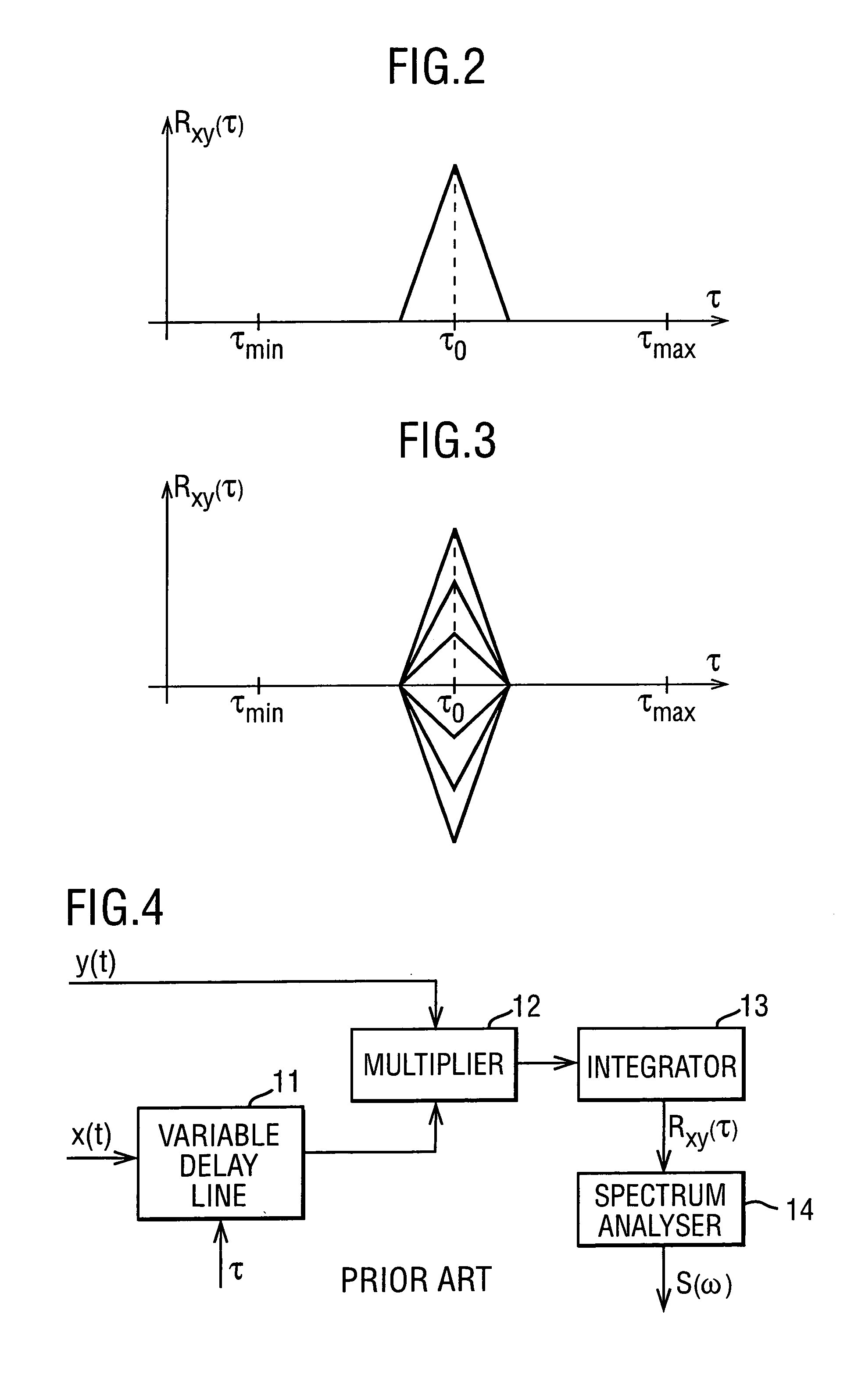
However, in most practical cases it is assumed that the small changes in range D, of the order of the wavelength of the carrier frequency, cannot be discerned when determining a short-time time-delay estimate.
Because of this approximation, such systems can only provide suboptimal solutions to the problem of joint estimation of time delay and Doppler frequency.

Method used


Image

  • Signal detection
  • Signal detection
  • Signal detection

Examples


Embodiment Construction

[0068]FIG. 7 shows a representation of the time-frequency plane divided into range-Doppler resolution cells and a hypothetical obstacle occupying a single cell. Prior art arrangements are designed to establish the coordinates τ0,ωD0 of the cell.

[0069]When obstacles are to be classified into only two alternative classes: obstacles moving with specified velocities and all other obstacles, the time-frequency plane will be divided into a number of resolution cells equal to the number of required range cells. An obstacle detected in any of those resolution cells will have the range specified by that cell, but its velocity may be one of the plurality of admissible velocities, corresponding to an entire interval of Doppler frequencies ωD, say, ωDminDDmax.

[0070]FIG. 8 is a representation of the time-frequency plane divided into a number of range resolution cells for a specified interval of Doppler frequencies. An obstacle located at the range cell To may have a radial velocity within an int...


PUM


Abstract

A transmitted signal and a received signal are combined and the combination is expected to determine whether or not a target signal is present. Either the transmitted signal or the received signal is combined with an auxiliary signal containing a range of frequencies corresponding to an anticipated Doppler shift, so that an output of the combined transmitted and received signal will be present only if a target signal exhibiting a Doppler shift within the anticipated range is present. The auxiliary signal preferably comprises finite-duration signal portions of different types so as to provide a substantially uniform frequency response throughout the selected range.

Description

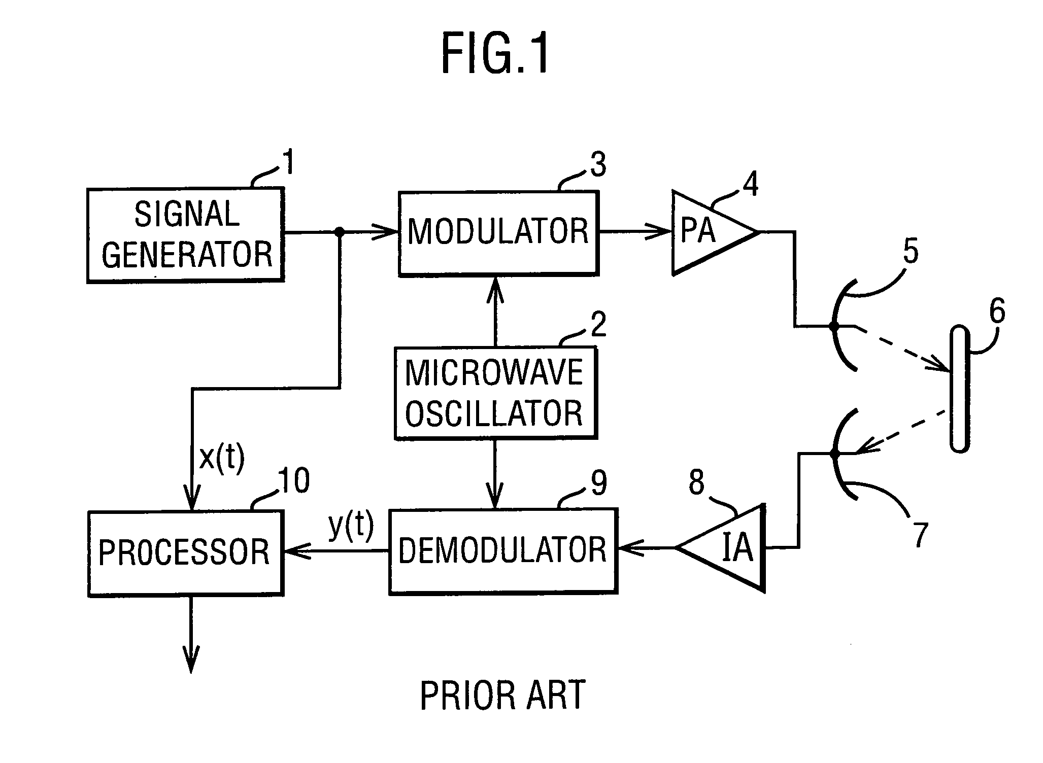
[0001]This is a divisional application of U.S. Patent application No. 10 / 112,873, filed Apr. 2, 2002 now U.S. Pat. No. 6,753,803FIELD OF THE INVENTION[0002]This invention relates to a method and apparatus for detecting signals. The invention is especially, but not exclusively, applicable to systems which may be subject to an unknown Doppler frequency shift affecting modulated coherent signals used for communication and ranging purposes, and particularly substantially continuous signals modulated by random or chaotic waveforms utilized by obstacle detection or collision avoidance systems.BACKGROUND OF THE INVENTION[0003]Such systems are designed to operate in multiuser and often hostile environments, and are intended for a wide range of applications, including automotive applications, industrial robotics and unmanned vehicle navigation.[0004]FIG. 1 is a block diagram of a typical microwave obstacle-detection system. The system comprises a signal generator 1 that produces a substantia...

Claims


Application Information

Patent Timeline
Patent Type & Authority Patents(United States)
IPC IPC(8): G01S13/58G01S13/50G01S13/52
CPCG01S13/52
Inventor SZAJNOWSKI, WIESLAW JERZY
Owner MITSUBISHI ELECTRIC CORP
Learn More