Carbon-Deposit Protection System For A Sheathed-Element Glow Plug Having A Gas Conduit For Pressure Measurement

a technology of gas conduit and protection system, which is applied in the direction of lighting and heating apparatus, applications, instruments, etc., can solve the problems that carbon residues or combustion residues cannot reach the particularly sensitive pressure sensor

Inactive Publication Date: 2008-03-20
ROBERT BOSCH GMBH
View PDF0 Cites 2 Cited by
  • Summary
  • Abstract
  • Description
  • Claims
  • Application Information

AI Technical Summary

Benefits of technology

[0011] It is an object of the invention to present a sheathed-element glow plug in which the penetration of carbon residues or

Problems solved by technology

The filter element obstructs the gas conduit extending next to or within the sheathed-element glow plug

Method used


Image

  • Carbon-Deposit Protection System For A Sheathed-Element Glow Plug Having A Gas Conduit For Pressure Measurement
  • Carbon-Deposit Protection System For A Sheathed-Element Glow Plug Having A Gas Conduit For Pressure Measurement
  • Carbon-Deposit Protection System For A Sheathed-Element Glow Plug Having A Gas Conduit For Pressure Measurement

Examples


Embodiment Construction

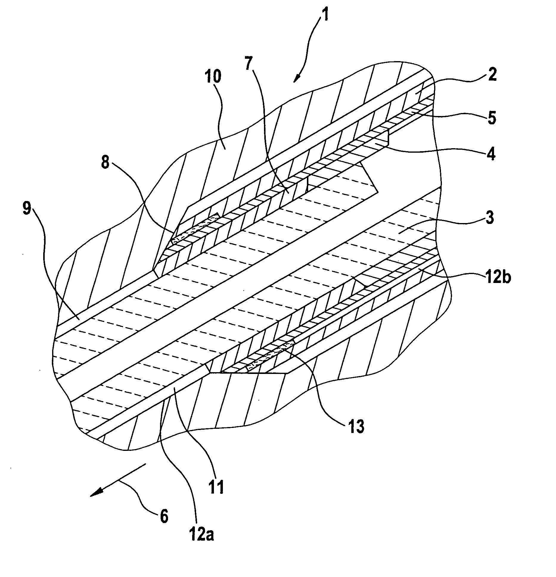
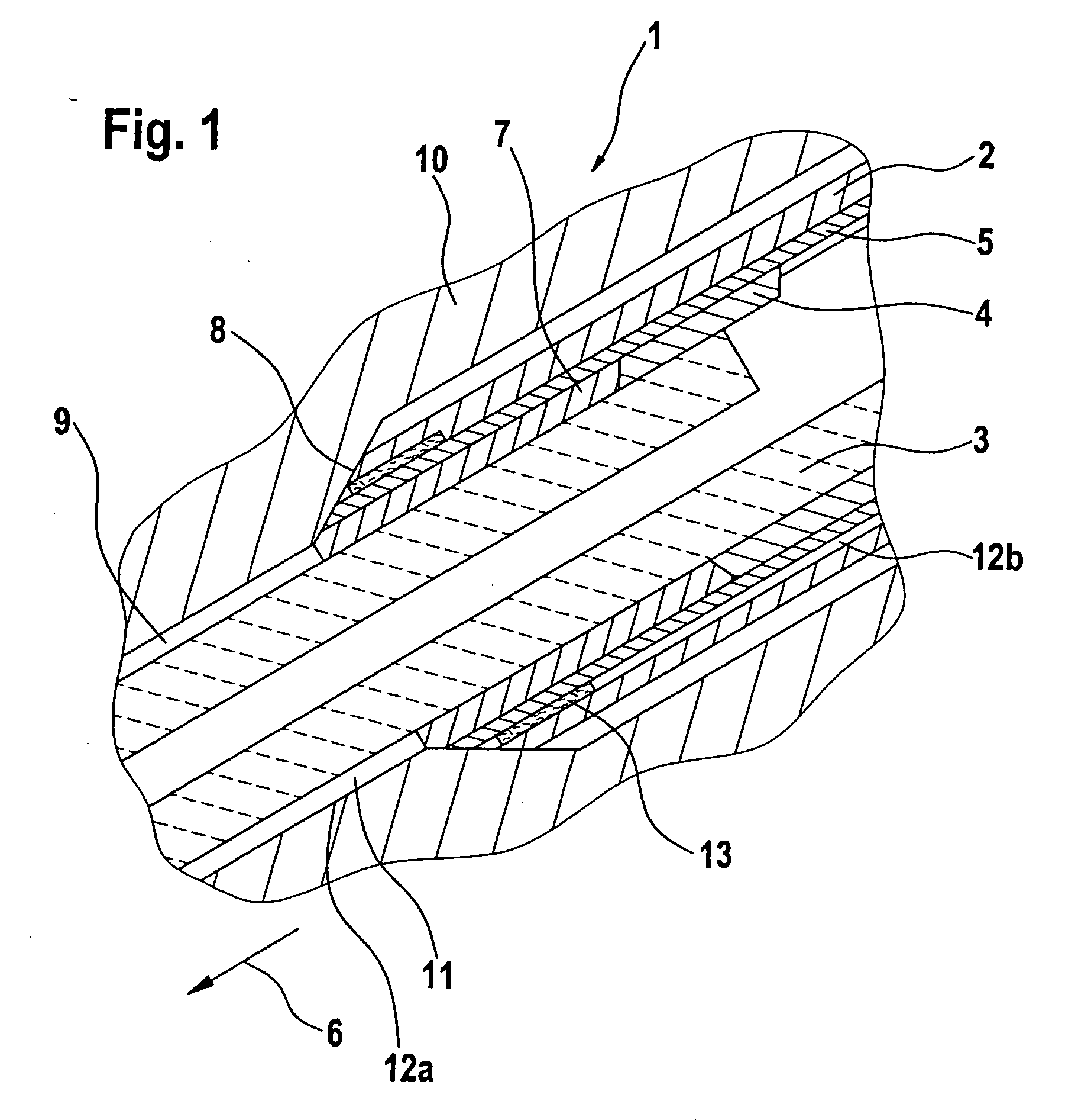
[0022] In an advantageous embodiment, the gas conduit of a sheathed-element glow plug is made up of two sub-segments: a first conduit that is formed by the open space between the glow element and the cylinder head orifice, and a second conduit that is located in a region between the glow element and the plug housing.

[0023] The filter element can be disposed in the first conduit or in the second conduit.

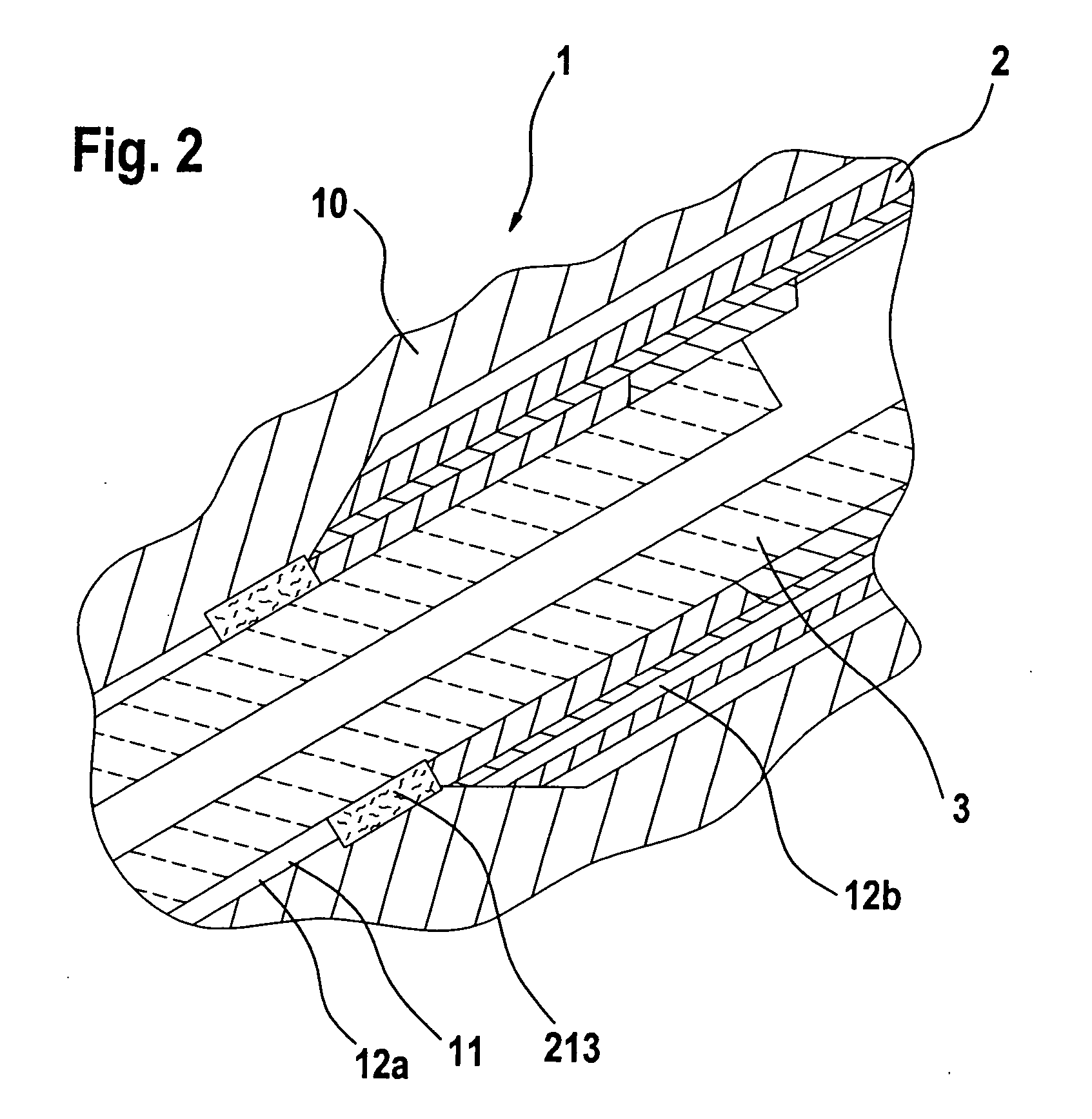
[0024] The filter element is preferably located in a region of the sheathed-element glow plug that is either sufficiently hot, or sufficiently heatable, that carbon residues in the filter element are collected or combusted. The filter element is placed for that purpose in the immediate vicinity of the glow element, and preferably forms a direct or at least positively engaged connection to the glow element. This can be effected, for example, by insertion, press-fitting, or plug-fitting.

[0025] In an advantageous embodiment, the filter element is joined to a sealing element that ensur...


PUM


Abstract

A sheathed-element glow plug for an internal combustion engine, made up substantially of a plug housing and a glow element disposed in the plug housing, having a gas conduit for measuring the combustion chamber pressure. A gas-permeable filter element, provided according to the present invention in the gas conduit, prevents the penetration of carbon residues or combustion residues into the interior of the sheathed-element glow plug, or reduces particle entry to a tolerable level.

Description

FIELD OF THE INVENTION [0001] The invention relates to a sheathed-element glow plug for an internal combustion engine, made up substantially of a plug housing and a glow element disposed in the plug housing, having a gas conduit for measuring the combustion chamber pressure. DESCRIPTION OF RELATED ART [0002] For good starting and warmup behavior at low temperatures, diesel engines require a heat source that preheats either the gas mixture, the intake air, or the combustion chamber. For passenger-car engines, the use of sheathed-element glow plugs is generally proposed. These encompass a plug housing and a glow element that projects out of the plug housing and, in its installed state, projects out of the cylinder head into the combustion chamber of an internal combustion engine. As a rule, the glow elements of the sheathed-element glow plugs project 4 mm into the combustion chamber of the internal combustion engine, and heat the diesel / air mixture. The glow temperature that is reache...

Claims


Application Information

Patent Timeline
IPC IPC(8): F23Q7/22F02P19/00F02P19/02F23Q7/00G01L19/06G01L23/22
CPCF02D35/023F02P19/028G01L19/0636G01L23/22F23Q2007/002F23Q7/001
Inventor KERN, CHRISTOPHSCHOTT, STEFFENBECK, MICHEL
Owner ROBERT BOSCH GMBH
Why Eureka
Try Eureka