
Toolessly adjustable cupola and photocontrol receptacle assembly

a technology of photocontrol and assembly, which is applied in the direction of coupling device connection, optical radiation measurement, instruments for comonautical navigation, etc., can solve the problems of time-consuming and frustrating process, process can also be time-consuming and frustrating

Active Publication Date: 2008-03-20
ABL IP HLDG
View PDF2 Cites 7 Cited by
  • Summary
  • Abstract
  • Description
  • Claims
  • Application Information

AI Technical Summary

Benefits of technology

The present invention provides a cupola and photocontrol receptacle assembly that allows a user to adjust the direction of the cupola base and the photocontrol receptacle simultaneously without using tools. The assembly includes a fixture housing with an opening for receiving a photocontrol receptacle connection member and ribs located in proximity to the fixture housing opening. The cupola base has an opening for receiving the connection member and features adapted to detachably engage the fixture housing ribs. A spring is coupled to the connection member and can pull the cupola base in one direction or the other, depending on the force applied. The assembly also includes a photocontrol receptacle with a base portion and a connection member, and a fixture housing with an opening for receiving the connection member and ribs. The assembly allows for easy adjustment of the photocontrol receptacle and maintains alignment with the cupola base window.

Problems solved by technology

This process can be time consuming and frustrating to a user.
This process can also be time consuming and frustrating, especially if the user must repeat this procedure due to the changing lighting conditions around the cupola and / or a desire for changing the amount of light receivable by the photocontrol.

Method used


Image

  • Toolessly adjustable cupola and photocontrol receptacle assembly
  • Toolessly adjustable cupola and photocontrol receptacle assembly
  • Toolessly adjustable cupola and photocontrol receptacle assembly

Examples


Embodiment Construction

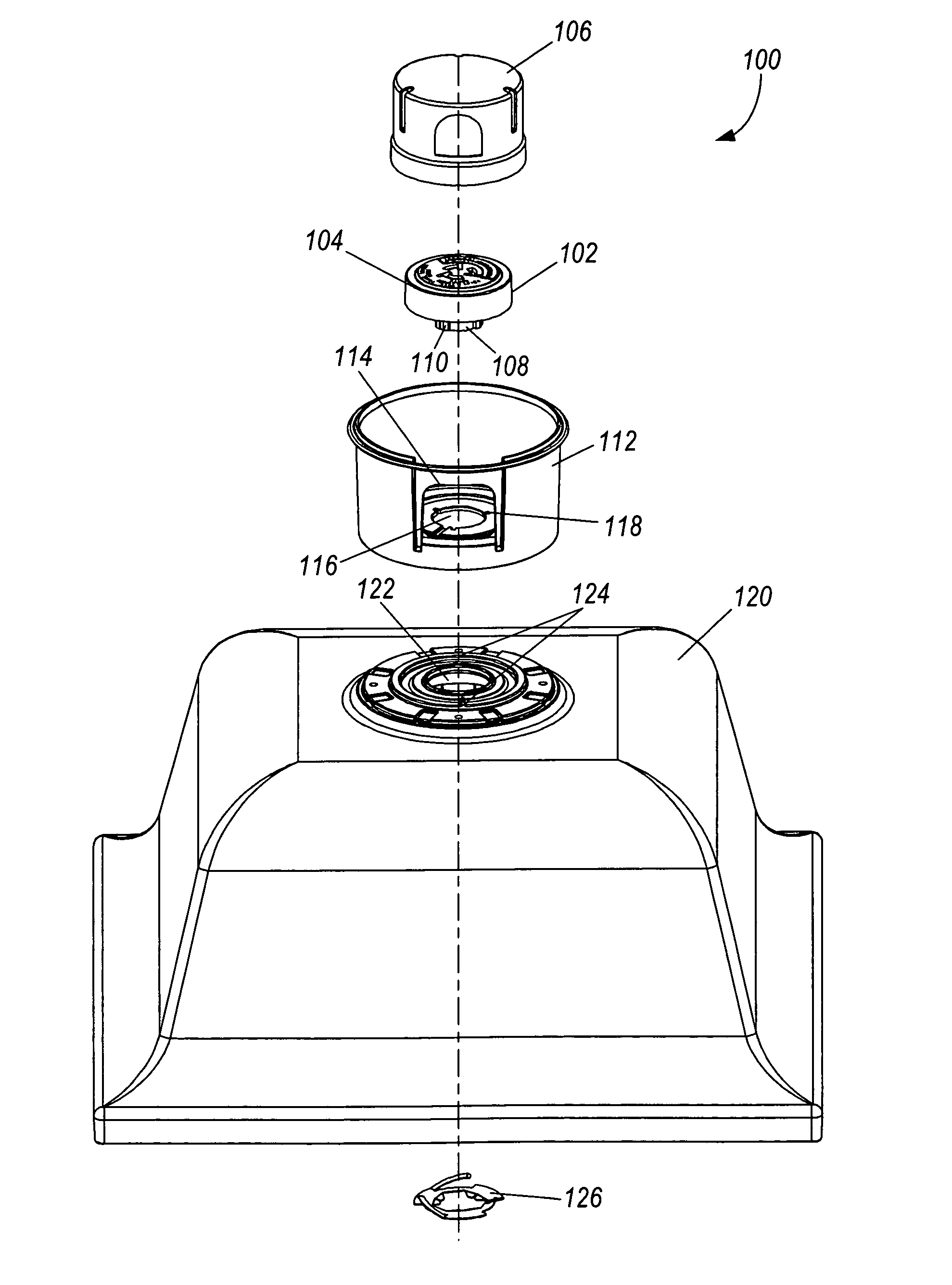
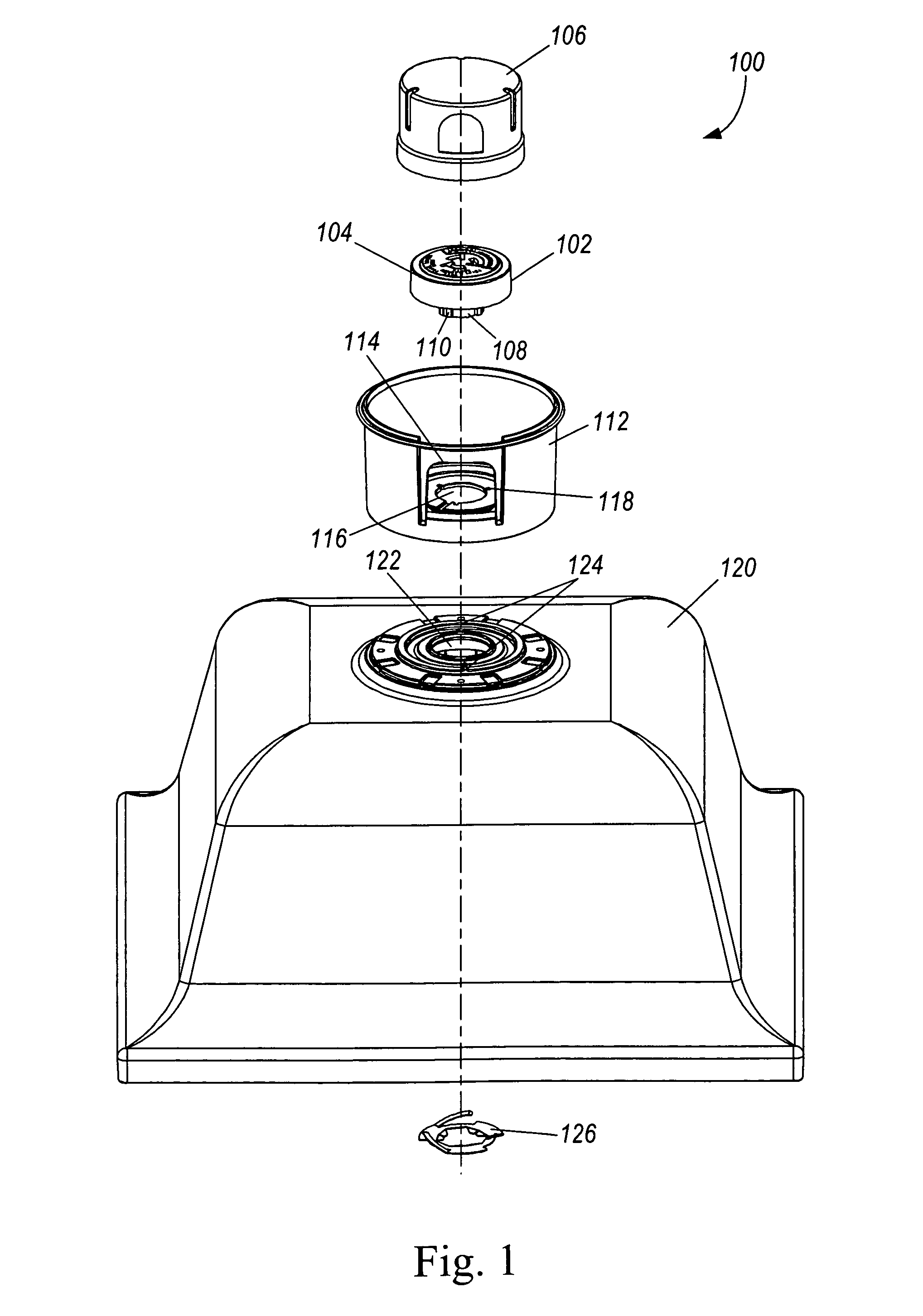
[0027]FIG. 1 shows one embodiment of an unassembled cupola and photocontrol unit 100. The unit 100 includes a photocontrol receptacle 102 with a base portion 104 that is generally circular and configured to connect with a photocontrol 106. The photocontrol receptacle 102 also includes a connection member 108 extending from the base portion 104. The connection member 108 includes flanges 110 extending outwardly relative to the connection member 108 for engaging a cupola base 112.

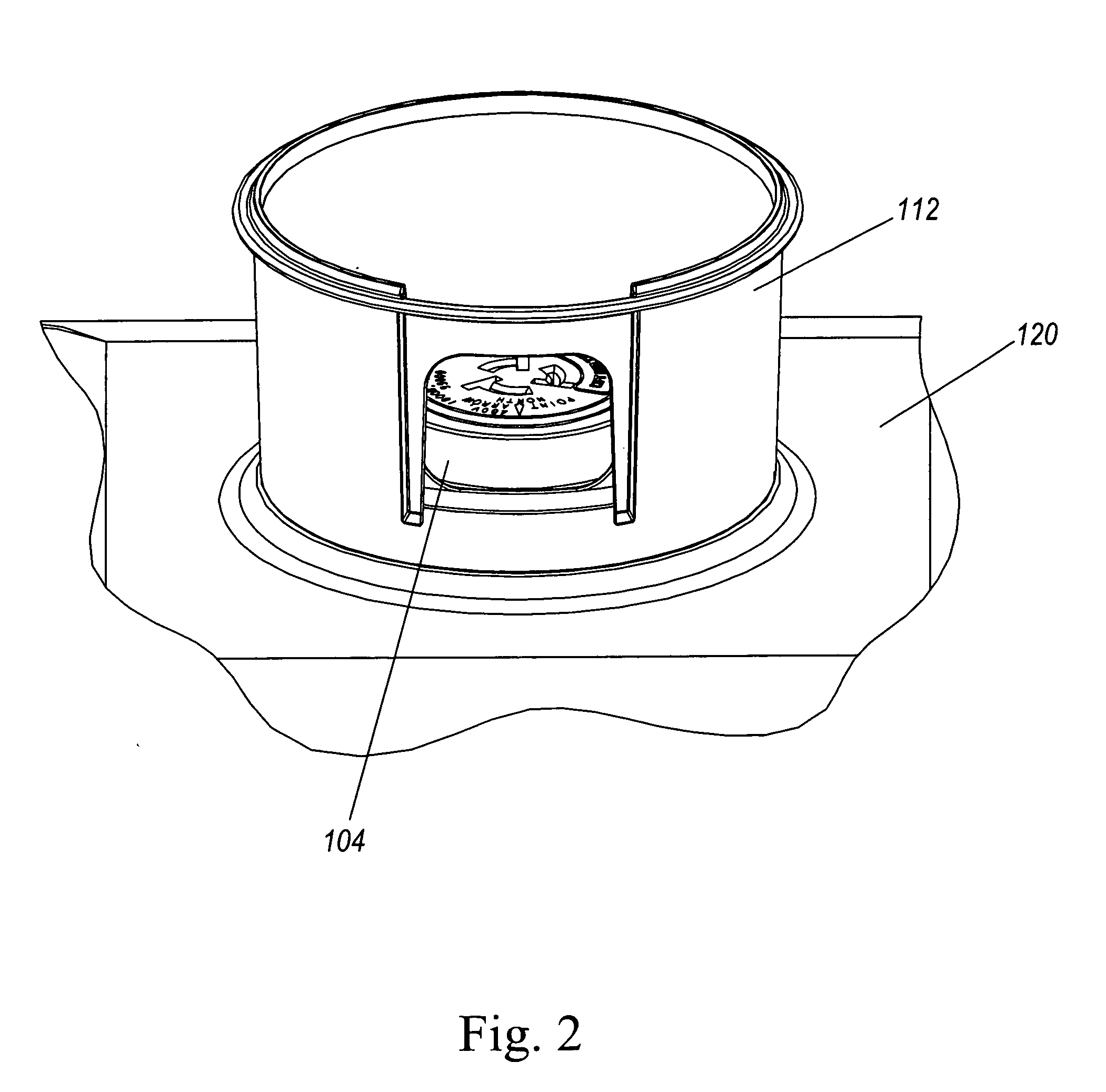
[0028]The cupola base 112 includes a window 114 to allow the photocontrol 106 to monitor the presence of light outside of the cupola base 112 and an opening 116 in the bottom of the cupola base 112. The cupola base 112 also includes one or more features (not shown) located on the bottom surface. The cupola base opening 116 is configured to receive the connection member 108 and includes notches 118 configured to receive the connection member flanges 110. When the connection member flanges 110 are received by t...


PUM


Abstract

Certain embodiments of the present invention provide a cupola and photocontrol receptacle assembly that allows a user to adjust the direction of the cupola base and the photocontrol receptacle simultaneously without using tools. A fixture housing may have an opening for receiving a photocontrol receptacle connection member and one or more ribs located in proximity to the fixture housing opening. A cupola base may include an opening for receiving the connection member and features adapted to detachably engaged the fixture housing ribs. In addition, a spring may be coupled to the connection member and configured to allow the photocontrol receptacle to move in a first direction upon the application of a force in the first direction and recoil when the force is removed or decreased.

Description

FIELD OF THE INVENTION[0001]The present invention relates generally to a cupola and photocontrol receptacle assembly that allows a user to adjust the cupola and photocontrol receptacle without the use of tools.BACKGROUND OF THE INVENTION[0002]A decorative covering, or cupola, may be used to house a photocontrol receptacle and / or photocontrol and attached to an outdoor light fixture. Generally, a photocontrol is a sensor that monitors the amount of light available from light sources, for example the sun, other than the attached light fixture and controls the operation of the light source contained in the light fixture. For example, a photocontrol sensor may automatically turn the attached lights on at dusk and off at dawn.[0003]Conventional cupola assemblies include a housing attached to the light fixture with a cupola base secured, such as by using screws, to the housing. The photocontrol is contained in a cupola base and connected to a photocontrol receptacle. The photocontrol rece...

Claims


Application Information

Patent Timeline
Patent Type & Authority Applications(United States)
IPC IPC(8): G01C21/02
CPCF21V23/0442G01J1/04G01J1/0403G01J2001/4266G01J1/06G01J1/42G01J1/0466
Inventor STEVENS, JOHN D.HAND, MARK ANTHONYWILCOX, SHAWN
Owner ABL IP HLDG
Learn More