Arrester Disconnector Assembly Minimizing Explosive Separation

a technology of explosive separation and disconnector assembly, which is applied in the direction of spark gap details, emergency protective arrangements for limiting excess voltage/current, cartridge-magazine switches, etc., can solve the problems of low resistance to surge current produced by sudden high voltage conditions, low resistance to surge current, and line failure, so as to minimize the build-up of internal pressure in the disconnector assembly, the effect of minimizing the explosive separation of the disconnector assembly

Inactive Publication Date: 2008-03-20
HUBBELL INC
View PDF33 Cites 26 Cited by
  • Summary
  • Abstract
  • Description
  • Claims
  • Application Information

AI Technical Summary

Benefits of technology

[0012]A further objective of the present invention is to provide a disconnector assembly for an arrester that minimizes the explosive separation of the disconnector assembly but is adequate for disconnection upon arrester failure.
[0013]A further objective of the present invention is to provide a disconnector assembly for an arrester that minimizes the explosive separation of the disconnector assembly when exposed to high temperatures when not in service.
[0014]A still further objective of the present invention is to provide a disconnector assembly for an arrester in which the build-up of internal pressure in the disconnector assembly is minimized when exposed to high temperatures when not in service.
[0015]The foregoing objects are basically attained by p...

Problems solved by technology

Arresters offer high resistance to normal voltage across power lines, but offer very low resistance to surge currents produced by sudden high voltage conditions caused by, for example, lighting strikes, switching surge currents or temporary overvoltages.
However, upon arrester malfunction or failure, the high resistance state is not resumed, and the arrester continues to provide an electrical path from the power line to ground.
Ultimately, the line will fail due to a short circuit condition, and the arrester will require replacement.
If the arrester fails, the arrester 60 Hz fault current flows through the failed arrester and through the ground lead disconnector, which causes the ground lead disconnector to operate.
When voltage reaches a predet...

Method used


Image

  • Arrester Disconnector Assembly Minimizing Explosive Separation
  • Arrester Disconnector Assembly Minimizing Explosive Separation
  • Arrester Disconnector Assembly Minimizing Explosive Separation

Examples


Embodiment Construction

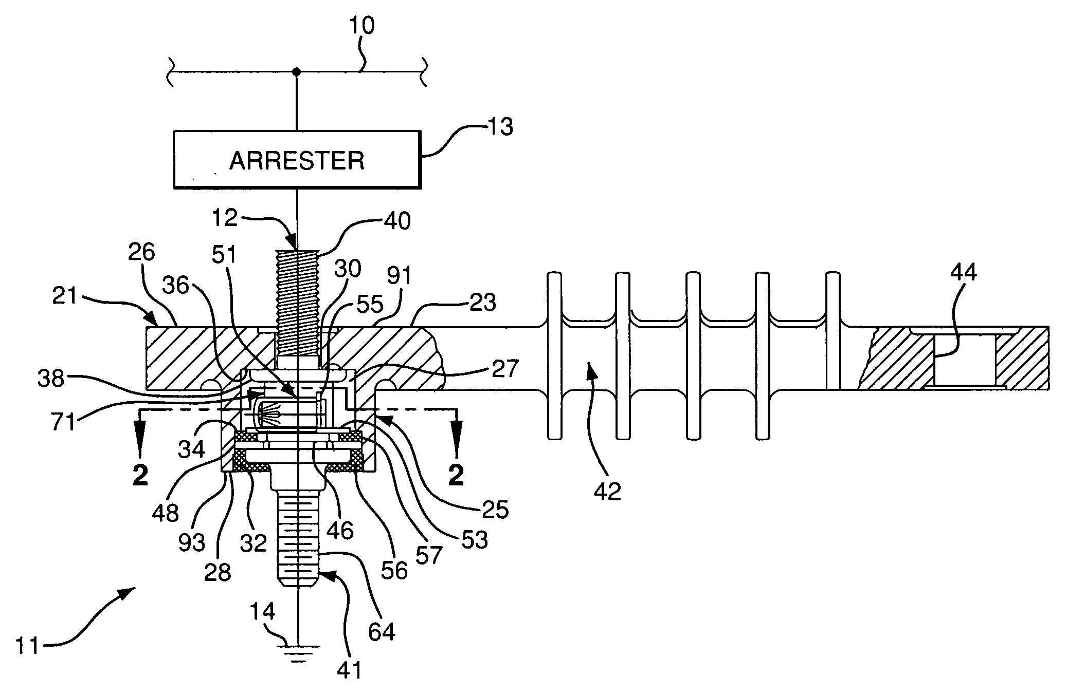
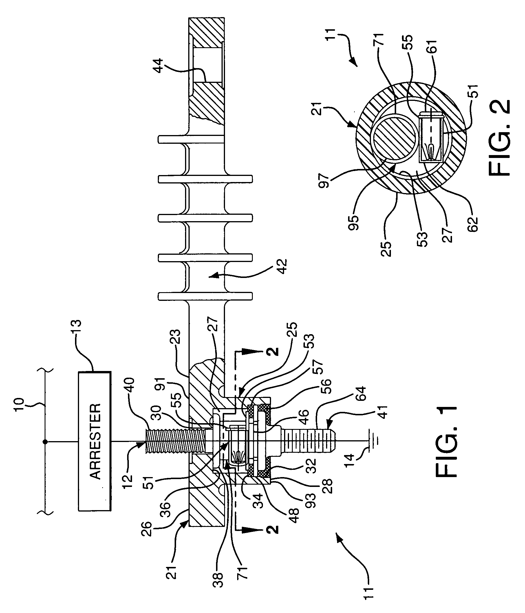
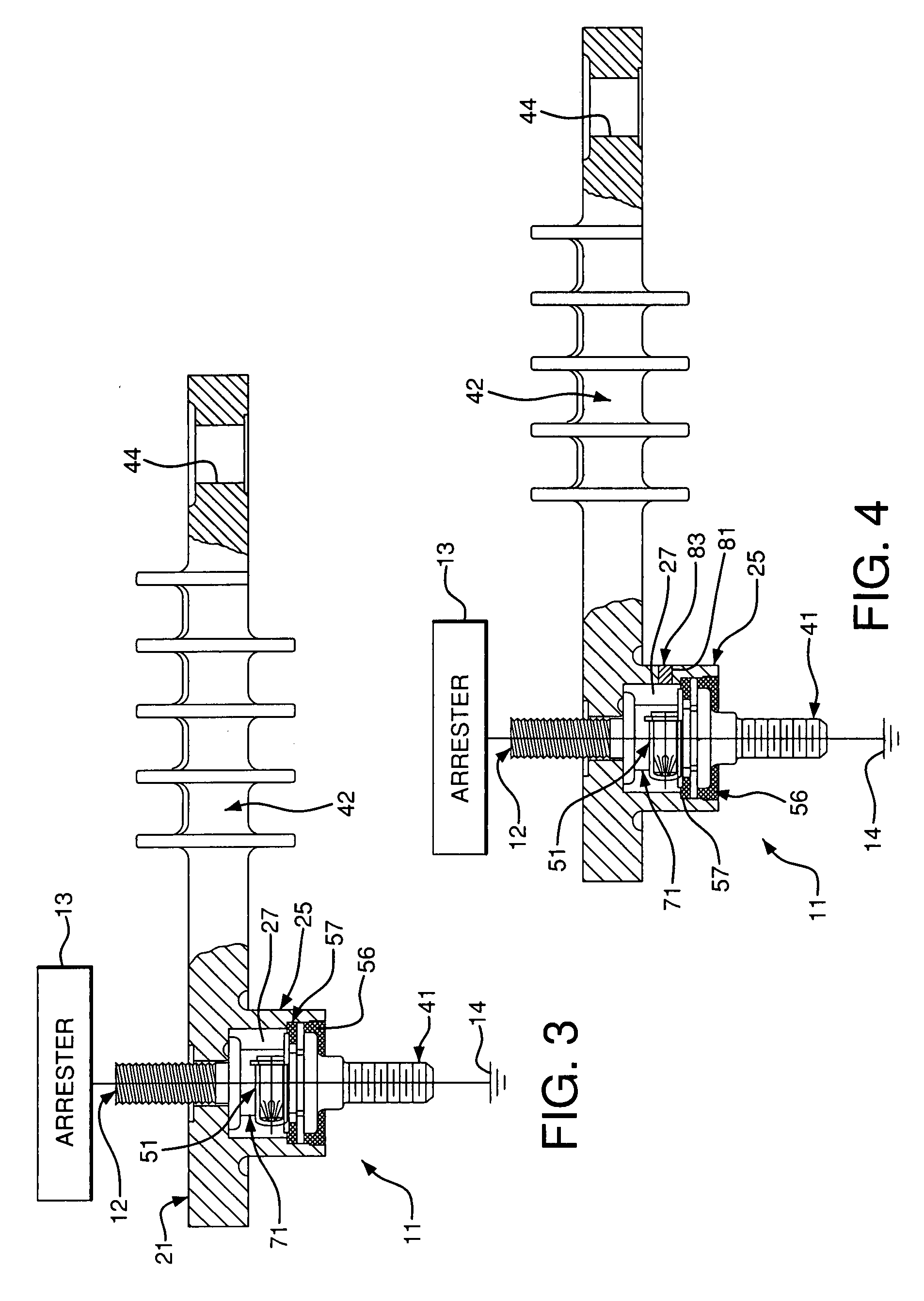
[0025]As shown in FIGS. 1-6, the present invention relates to a disconnector assembly 11 for an arrester 13 and connecting the arrester to ground 14. A non-conductive housing 21 has first and second opposite ends 91 and 93 separated by an internal chamber 27. A first electrical terminal 12 is connected at the first end 91. A second electrical terminal 41 is connected at the second end 93. A grading component 95 engages and extends between the first and second terminals 12 and 41 in the internal chamber 27. A cartridge 51 with an explosive charge is positioned in the internal chamber 27. A spring spacer 53 receives the cartridge 51. The spring spacer 53 is adjacent the second terminal 41 and spaced from the first terminal 12.

[0026]Referring initially to FIGS. I and 2, a disconnector assembly 11, according to an exemplary embodiment of the present invention, includes a first, upper electrical terminal 12 electrically connected to an arrester 13 that is connected to a power line 10, an...


PUM


Abstract

A disconnector assembly for an arrester includes a housing having first and second opposite ends. A cavity is disposed within the housing. A first electrical terminal is disposed at the first end of the housing, and a second electrical terminal is disposed at the second end of the housing. A cartridge with an explosive charge disposed in the cavity between the first and second electrical terminals. The cartridge has a powder load greater than 0 grams and not greater than approximately 0.15 grams. The powder load is sufficient to separate said second electrical terminal from said first electrical terminal upon cartridge detonation while minimizing the intensity of the explosive separation upon unintended cartridge detonation.

Description

CROSS REFERENCE TO RELATED APPLICATIONS [0001]This application claims the benefit under 35 U.S.C. § 119(e) of provisional patent application Ser. Nos. 60 / 844,670, filed Sep. 15, 2006 and 60 / 826,021, filed Sep. 18, 2006, both of which are hereby incorporated by reference in their entirety.FIELD OF THE INVENTION [0002]The present invention relates to a disconnector assembly for an arrester that minimizes the explosive separation of the disconnector assembly. More particularly, the present invention relates to a disconnector assembly in which the detonation charge is reduced to minimize the explosive separation of the disconnector assembly. More particularly, the present invention relates to a disconnector assembly in which the build up of internal pressure in the disconnector assembly is reduced.BACKGROUND OF THE INVENTION [0003]Lighting or surge arresters are typically connected to power lines to carry electrical surge currents to ground, thereby preventing damage to lines and equipm...

Claims


Application Information

Patent Timeline
IPC IPC(8): H01H39/00
CPCH01T1/14H01H39/002
Inventor LENK, DENNIS W.PRICE, JAMES P.KRAUSE, JOHN A.
Owner HUBBELL INC
Why Eureka
Try Eureka