Ultracapacitor pressure control system

Inactive Publication Date: 2007-06-28
UCAP POWER INC
View PDF18 Cites 51 Cited by
  • Summary
  • Abstract
  • Description
  • Claims
  • Application Information

AI Technical Summary

Benefits of technology

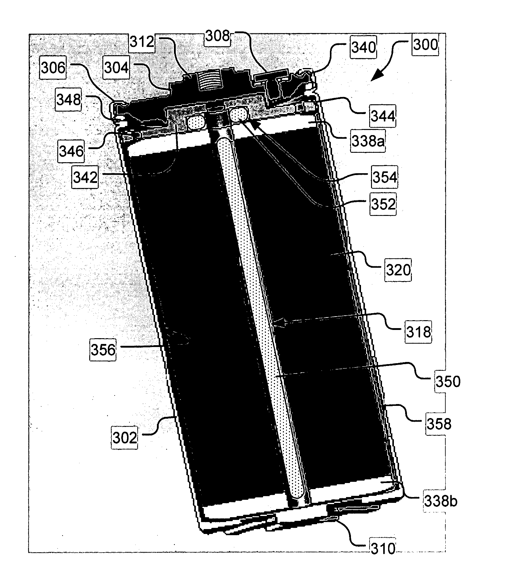
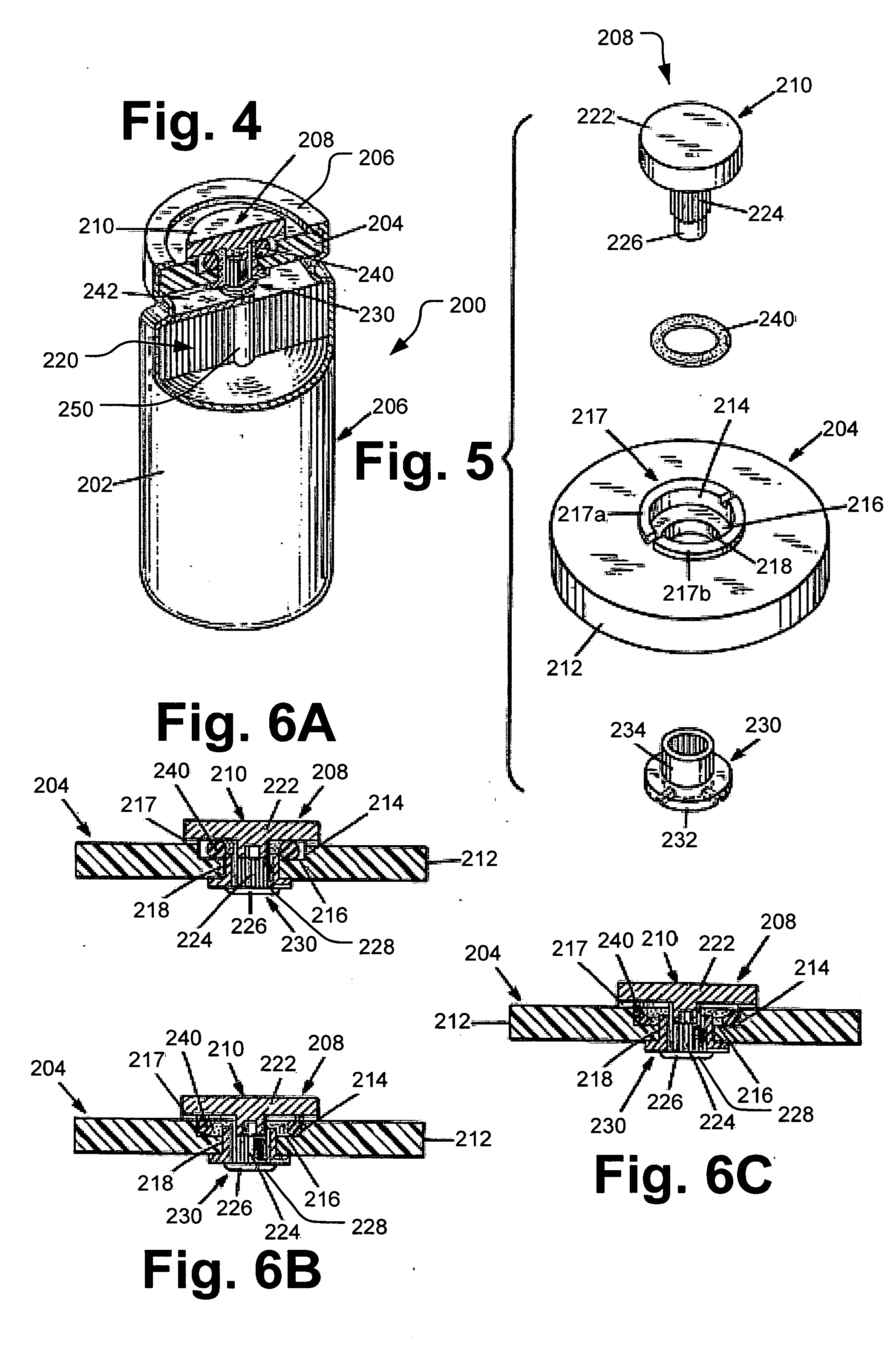
[0009] A resealable vent may additionally be used to reduce gas pressure in a cell and direct the gas to a gas getter for collection. The cell may be one of several cells in a module. The gas getter may be placed in the module in order to capture the gas released through the vents in each of the cells in the module. The module may or may not be hermetically sealed depending upon the type of gas getter formulation used and whether the gas getter is resistant to atmospheric gasses and moisture. The vents may incorporate either a spring or an elastomeric or resilient material, which depresses or deforms under pressure to expose a vent hole, thus allowing the gas to escape. After the pressure is reduced, the spring, elastomer, or other resilient material returns to a low pressure d

Problems solved by technology

The trapped gas causes the internal pressure of the capacitor to rise, eventually causing the cell package to rupture.
Once the cell package or fuse ruptures, the ultracapacitor is no longer functional.
If the vent is stuck open, water vapor may enter the cell and

Method used


Image

  • Ultracapacitor pressure control system
  • Ultracapacitor pressure control system
  • Ultracapacitor pressure control system

Examples


Embodiment Construction

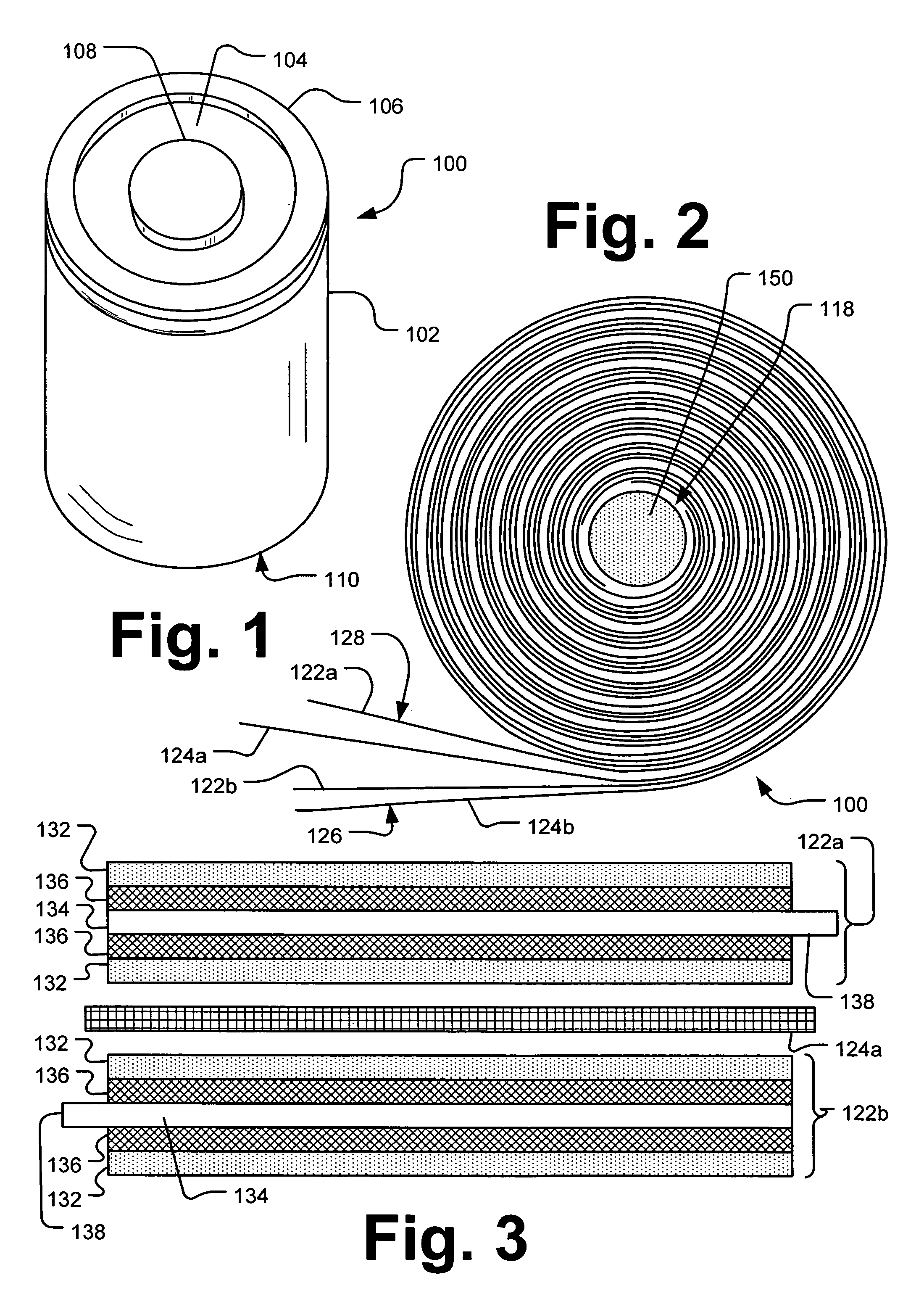
[0021] Capacitors store energy in an electric field between a pair of closely spaced conductors (called “plates”). When voltage is applied to the capacitor, electric charges of equal magnitude, but opposite polarity, build up on each plate and thereby store energy. “Double-layer” capacitors store electrostatic energy across an electrical potential formed between sheets of electrode films and associated collecting plates immersed in an electrolyte. A polarized electrode-electrolyte interface layer is created when a finished capacitor cell is immersed in the electrolyte. When the sheets are immersed in the electrolyte, a first layer of electrolyte dipole and a second layer of charged species is formed. Double-layer capacitor technology is also referred to as “ultracapacitor” technology and “supercapacitor” technology. Such double-layer capacitors can be obtained from Maxwell Technologies, Inc., (San Diego Calif.).

[0022] In comparison to conventional capacitors, double-layer capacitor...


PUM


Abstract

An ultracapacitor design minimizes the internal pressure of the cell package by using gas getters, either alone or in combination with a resealable vent in the package. Reducing pressure extends the life of the ultracapacitor. The primary gas types generated within a particular ultracapacitor are measured under multiple possible application conditions. Such conditions may include variables of temperature, application voltage, electrolyte type, length of use, and cycles of use. The primary gas components may be determined and suitable gas getters for different conditions may be formulated. The gas getters may be packed within the ultracapacitor packages, formulated as a negative electrode, doped into the negative current collector, or layered with the negative current collector.

Description

CROSS REFERENCE TO RELATED APPLICATIONS [0001] This application claims the benefit of priority pursuant to 35 U.S.C. § 119(e) of U.S. provisional application Nos. 60 / 739,203 filed 22 Nov. 2005 entitled “Resealable vent for capacitors” and 60 / 748,897 filed 8 Dec. 2005 entitled “Minimizing internal pressure by gas getter for high voltage ultracapacitor,” which are hereby incorporated herein by reference in their entirety.BACKGROUND [0002] 1. Technical Field [0003] The subject matter described herein relates to methods for reduction of pressure due to gas build-up in ultracapacitors. [0004] 2. Description of the Related Art [0005] During high voltage charge of an ultracapacitor, particularly in combination with high temperatures, gases are generated due to thermal evaporation, chemical reactions, and electrochemical reactions. The gas generated is trapped within the capacitor packaging. The trapped gas causes the internal pressure of the capacitor to rise, eventually causing the cell p...

Claims


Application Information

Patent Timeline
IPC IPC(8): H01G9/00H01G15/00
CPCY02E60/13H01G11/82H01G11/20Y02T10/7022Y02T10/70H01G9/12H01G9/08
Inventor MITCHELL, PORTERCRAWFORD, ROBERTXI, XIAOMEIZHONG, LINDA
Owner UCAP POWER INC
Why Eureka
Try Eureka