Procedure for addressing remotely-located radio frequency components of a control system

a control system and radio frequency technology, applied in the direction of electrical programme control, testing/monitoring control system, instruments, etc., can solve the problems of impracticality of contact with the load control device during the addressing procedure, and the inability to adapt the prior addressing procedure to address the rf load control device,

Active Publication Date: 2008-03-20
LUTRON TECH CO LLC
View PDF76 Cites 65 Cited by
  • Summary
  • Abstract
  • Description
  • Claims
  • Application Information

AI Technical Summary

Benefits of technology

[0015]According to the present invention, a method for assigning a unique device address to a remotely-located control device in a lighting control system comprises the steps of (1) applying power to the control device; (2) th

Problems solved by technology

The prior addressing procedure, however, is not adapted for addressing RF load control devices that may be mounted in relatively inaccessible locations.
For example, load control devices, such as electronic dimming ballasts, motorized window treatments, or remote dimmer modules, may be mounted in remote locations such that contact with the load control device during the addressing procedure is rendered impractical.
Because of the relatively large size of

Method used


Image

  • Procedure for addressing remotely-located radio frequency components of a control system
  • Procedure for addressing remotely-located radio frequency components of a control system
  • Procedure for addressing remotely-located radio frequency components of a control system

Examples


Embodiment Construction

[0025]The foregoing summary, as well as the following detailed description of the preferred embodiments, is better understood when read in conjunction with the appended drawings. For the purposes of illustrating the invention, there is shown in the drawings an embodiment that is presently preferred, in which like numerals represent similar parts throughout the several views of the drawings, it being understood, however, that the invention is not limited to the specific methods and instrumentalities disclosed.

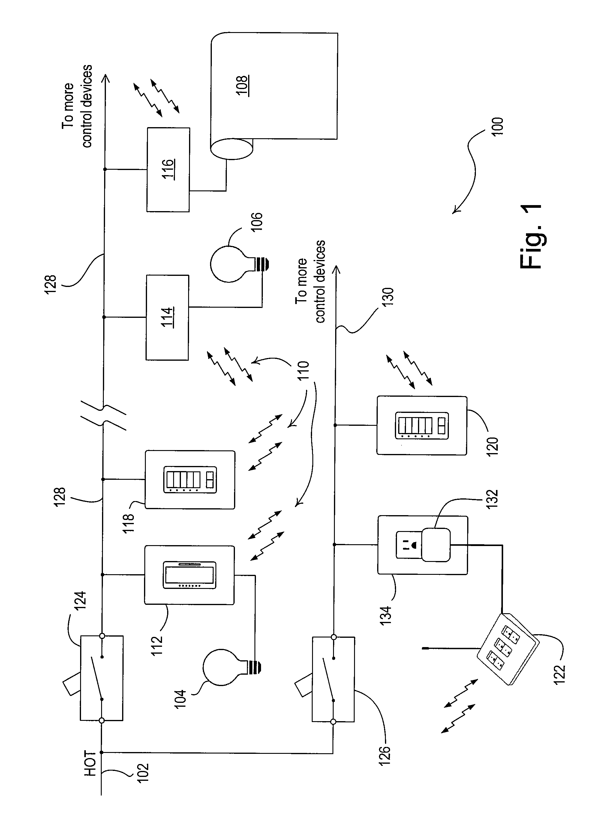
[0026]FIG. 1 is a simplified block diagram of an RF lighting control system 100 according to the present invention. The RF lighting control system 100 is operable to control the power delivered from a source of AC power to a plurality of electrical loads, for example, lighting loads 104, 106 and a motorized roller shade 108. The RF lighting control system 100 includes a HOT connection 102 to a source of AC power for powering the control devices and the electrical loads of the li...


PUM


Abstract

The present invention provides a method of assigning a unique device address to a remotely-located control device in a wireless lighting control system having a plurality of control devices. Each of the control devices is operable to couple to a source of power and to be assigned a unique device address. The method first comprises cycling power to the remotely-located control devices, i.e., interrupting and restoring power to the control devices. The control device transmits wirelessly a signal uniquely identifying the control device within a predetermined amount of time after the cycling of power. A list of unaddressed control devices that have recently been power cycled is generated. Each of the control devices on the list is then assigned and transmitted a unique device address.

Description

BACKGROUND OF THE INVENTION[0001]1. Field of the Invention[0002]The present invention relates to load control systems for controlling electrical loads and more particularly to a procedure for addressing remotely-located control devices of a radio frequency (RF) lighting control system.[0003]2. Description of the Related Art[0004]Control systems for controlling electrical loads, such as lights, motorized window treatments, and fans, are known. Such control systems often use radio frequency (RF) transmission to provide wireless communication between the control devices of the system. Examples of RF lighting control systems are disclosed in commonly-assigned U.S. Pat. No. 5,905,442, issued on May 18, 1999, entitled METHOD AND APPARATUS FOR CONTROLLING AND DETERMINING THE STATUS OF ELECTRICAL DEVICES FROM REMOTE LOCATIONS, and commonly-assigned U.S. Pat. No. 6,803,728, issued Oct. 12, 2004, entitled SYSTEM FOR CONTROL OF DEVICES. The entire disclosures of both patents are hereby incorpo...

Claims


Application Information

Patent Timeline
IPC IPC(8): G05B23/02G05B19/02
CPCH05B37/0272H05B47/19Y02B20/40
Inventor JOHNSON, BENJAMIN A.MIERTA, JUSTINCOURTNEY, BRIAN MICHAELCARMEN, LAWRENCE R.RANERI, DANIEL CURTIS
Owner LUTRON TECH CO LLC
Why Eureka
Try Eureka