Communication apparatus and coexistence method for enabling coexistence of communication systems

a communication system and coexistence method technology, applied in the field of communication apparatus and coexistence method for enabling coexistence of communication systems, can solve problems such as loss of audio information, sense of discomfort, and increase in delay tim

Active Publication Date: 2007-05-03
PANASONIC CORP
View PDF3 Cites 39 Cited by
  • Summary
  • Abstract
  • Description
  • Claims
  • Application Information

AI Technical Summary

Benefits of technology

[0025] Therefore, an object of the present invention is to provide a communication apparatus and a coexistence method in which coexistence can be achieved while satisfying AV-QoS in a plurality of different communi

Problems solved by technology

However, in the case of VoIP, a sense of discomfort occurs as a delay time increases in voice signals.
The packet discarding leads to loss of audio information.
As the frequency of the packet discarding increases, discontinuity or noise occurs in audio.
On the other hand, in the case of video distribution, a large amount of data needs to be communicated.
As the beacon cycle decreases, a data delay can be suppressed to a smaller level, but a data amount transmitted by one packet decreases, so that the proportion of overhead, such as header information and the like, increases, resulting in a decrease in transmission efficiency.
As described above, various forms of power line communication from a ho

Method used


Image

  • Communication apparatus and coexistence method for enabling coexistence of communication systems
  • Communication apparatus and coexistence method for enabling coexistence of communication systems
  • Communication apparatus and coexistence method for enabling coexistence of communication systems

Examples


first embodiment

[0052] (First Embodiment)

[0053] In a first embodiment, an example in which three communication systems are caused to coexist using Time Division Multiplexing (TDM), will be described.

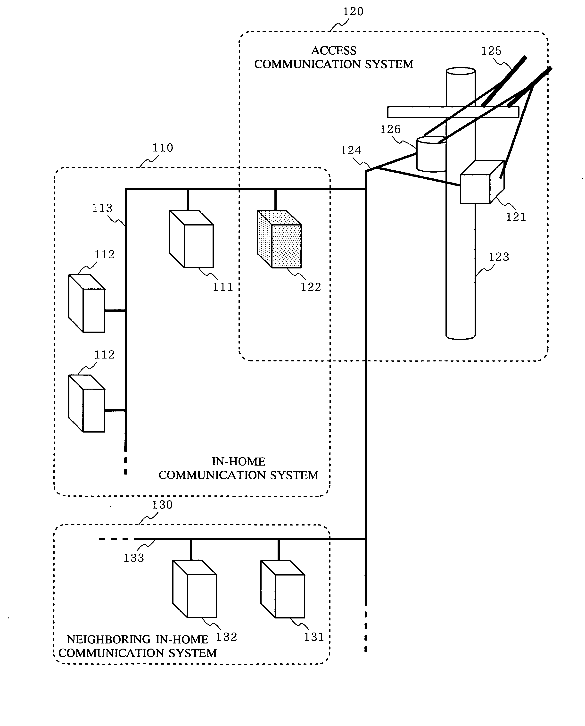
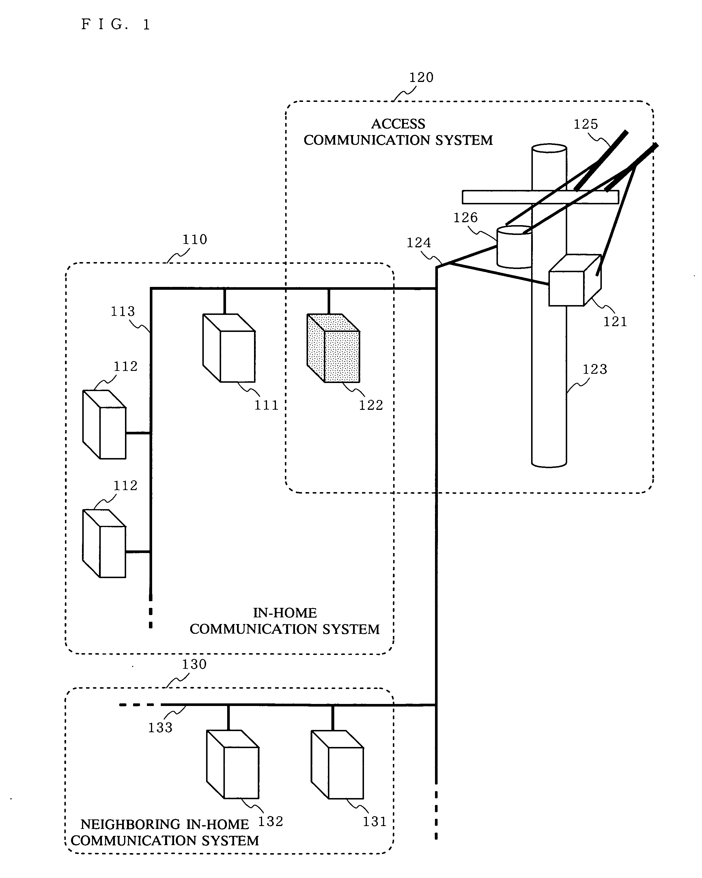
[0054]FIG. 1 is a diagram schematically illustrating a configuration of a communication system which employs a communication apparatus according to the first embodiment of the present invention. In the first embodiment, there are three communication systems, i.e., in-home communication systems 110 and 130 and an access communication system 120. Note that the configuration of the communication system of FIG. 1 is only for illustrative purposes. The in-home communication system 110 and the in-home communication system 130 may be located in the same home, and there may be three or more in-home communication systems.

[0055] The in-home communication system 110 is a power line communication system which utilizes a power line 113 provided in a home, and is composed of an in-home-system master station 111 whi...

second embodiment

[0082] (Second Embodiment)

[0083] A method for causing a plurality of communication systems to coexist by time division performs a control based on a coexistence signal which each communication system transmits to other communication systems. Therefore, two communication systems between which a signal is not directly communicated may be caused to coexist and be in synchronization with each other via another communication system intervening therebetween.

[0084] However, there is also an apparatus which is powered only when it is used as well as an apparatus which is powered all the time, of electronic apparatuses belonging to an in-home communication system. Therefore, when the intervening communication system is powered OFF, the synchronization relationship between the two communication systems between which a signal is not directly communicated collapses. Therefore, when the intervening communication system is powered ON at the next time, a coexistence / synchronization control has to...


PUM


Abstract

In-home communication systems 110 and 130 and an access communication system 120 are caused to coexist by TDM in synchronization with a power cycle, and a communication system which needs to secure AV-QoS assigns transmission timing to a slave station in itself by synchronizing a beacon cycle with a cycle of a power line.

Description

BACKGROUND OF THE INVENTION [0001] 1. Field of the Invention [0002] The present invention relates to a communication apparatus and a coexistence method for enabling coexistence of communication systems. More particularly, the present invention relates to a technique of enabling coexistence of two communication systems which use the same communication medium and have different communication schemes (data communication is performed while maintaining AV-QoS (Audio Video-Quality of Services) required for video transmission and audio communication), a communication apparatus included in each of the communication systems, and a coexistence method which is executed by the communication apparatus. [0003] 2. Description of the Background Art [0004] Power line communication technology is a communication means for connection of a Personal Computer (PC) in a home to a network apparatus, such as a broadband router or the like, so as to access from the PC to the Internet. In the power line commun...

Claims


Application Information

Patent Timeline
IPC IPC(8): H04L12/66
CPCH04B3/54H04B2203/542H04B2203/545H04J3/0638H04J3/0644H04L12/2801H04L12/2803H04L12/66H04L2012/2843H04L7/02H04L12/28
Inventor KUROBE, AKIOKURODA, GOIKEDA, KOJIKOGA, HISAOIGATA, YUJI
Owner PANASONIC CORP
Why Eureka
Try Eureka